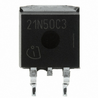
SPB21N50C3 Infineon Technologies, SPB21N50C3 Datasheet

SPB21N50C3
Specifications of SPB21N50C3
SP000013833
SPB21N50C3
SPB21N50C3INTR
SPB21N50C3XT
Available stocks
Related parts for SPB21N50C3
SPB21N50C3 Summary of contents
Page 1
... Reverse diode dv/dt Rev. 2.3 Ordering Code Q67040-S4566 Symbol puls jmax limited jmax limited jmax tot dv/dt Page 1 SPB21N50C3 @ T 560 V DS jmax R 0.19 DS(on PG-TO263 Marking 21N50C3 Value SPB 21 13.1 63 690 1 21 ±20 ±30 208 T -55...+150 stg 15 2005-11-07 V Ω A Unit ...
Page 2
... D I =500V, V =0V, V DSS DS GS =25° =150° =20V, V =0V V GSS GS DS =10V, I =13.1A V DS(on =25° =150° f=1MHz, open drain R G Page 2 SPB21N50C3 Value Unit 50 V/ns Values Unit min. typ. max 0 260 °C Values Unit min. typ. max. ...
Page 3
... D r =3.6Ω d(off =380V, I =21A =380V, I =21A 10V =380V, I =21A V D (plateau) DD =400V, V <V T <T peak BR, DSS, j j,max. Page 3 SPB21N50C3 Values min. typ. max 2400 - 1200 - 181 - 10 =0/10V 4 * while V is rising from 0 to 80% V oss DS while V is rising from 0 to 80% V ...
Page 4
... SD GS =380V /dt=100A/µ rrm di /dt =25° Unit Symbol K/W C th1 C th2 C th3 C th4 C th5 C th6 th1 th th1 th2 th,n Page 4 SPB21N50C3 Values min. typ 450 = 1200 Value SPB 0.0003763 0.001411 0.001931 0.005297 0.012 0.091 E xternal H eatsink T case Unit max 1 µC ...
Page 5
... SPP21N50C3 240 W 200 180 160 140 120 100 Safe operating area parameter : =25° 0.001 0. 0 Rev. 2.3 2 Power dissipation FullPAK = tot °C 100 120 160 Safe operating area FullPAK parameter Page 5 SPB21N50C3 ) 100 120 ) DS = 25° 0.001 0. 0 2005-11-07 °C 160 ...
Page 6
... Vgs = 7V Vgs = 6. Rev. 2.3 6 Transient thermal impedance FullPAK Z thJC parameter 0.01 10 single pulse Typ. output characteristic parameter: t Vgs = 6V Vgs = 5.5V Vgs = 5V Vgs = 4.5V Vgs = Page 6 SPB21N50C3 = =150° µ Vgs = 20V Vgs = 7V 30 Vgs = 6V Vgs = ...
Page 7
... Vgs = 4V Vgs = 4.5V 0.8 Vgs = 5V Vgs = 5.5V 0.7 Vgs = 6V Vgs = 20V 0.6 0.5 0.4 0.3 0.2 0 Typ. gate charge = DS(on)max GS parameter 150° Page 7 SPB21N50C3 = 13 SPP21N50C3 98% typ 0 -60 - 100 ) Gate = 21 A pulsed D SPP21N50C3 0 max 0 100 2005-11-07 °C 180 ...
Page 8
... Rev. 2.3 14 Avalanche SOA ≤ 150 °C par 2 Drain-source breakdown voltage V (BR)DSS 600 V 570 560 550 540 530 520 510 500 490 480 470 460 450 °C 120 160 - Page 8 SPB21N50C3 ) AR Tj(Start)=25°C Tj(Start)=125° SPP21N50C3 - 100 2005-11- µ °C 180 T j ...
Page 9
... Avalanche power losses parameter: E =1mJ AR 500 W 300 200 100 Typ. C stored energy oss E =f(V ) oss DS 10 µ 100 150 200 250 300 350 400 Rev. 2.3 18 Typ. capacitances parameter 500 V DS Page 9 SPB21N50C3 =0V, f=1 MHz GS Ciss Coss Crss 100 200 300 2005-11-07 500 ...
Page 10
... Definition of diodes switching characteristics Rev. 2.3 Page 10 SPB21N50C3 2005-11-07 ...
Page 11
PG-TO263-3-2, PG-TO263-3-5, PG-TO263-3-22 Rev. 2 11-07 ...
Page 12
... Life support devices or systems are intended to be implanted in the human body support and/or maintain and sustain and/or protect human life. If they fail reasonable to assume that the health of the user or other persons may be endangered. Rev. 2.3 Page 12 SPB21N50C3 2005-11-07 ...


