24140 Cinch Connectors, 24140 Datasheet - Page 4
24140
Manufacturer Part Number
24140
Description
Manufacturer
Cinch Connectors
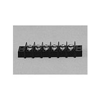
Type
Barrier Stripr
Datasheet
1.24140.pdf
(282 pages)
Specifications of 24140
Number Of Contacts
24POS
Number Of Contact Rows
2
Termination Method
Screw
Mounting Style
Panel
Contact Pitch (mm)
9.53mm
Current Rating (max)
15A
Operating Temp Range
-48C to 148C
Housing Material
Phenolic
Body Orientation
Straight
Operating Voltage (max)
250VAC
Product Height (mm)
28.58mm
Product Length (mm)
245.28mm
Wire Gauge
16
Lead Free Status / RoHS Status
Compliant
Available stocks
Company
Part Number
Manufacturer
Quantity
Price
Company:

Part Number:
241402B91200G
Manufacturer:
ATH
Quantity:
1 020
Company:
Part Number:
241402B92200G
Manufacturer:
ATH
Quantity:
414
Company:
Part Number:
241404B91200G
Manufacturer:
ATH
Quantity:
300
Company:
Part Number:
241404B92200G
Manufacturer:
ATH
Quantity:
262
Company:
Part Number:
241409B91200G
Manufacturer:
ATH
Quantity:
100


The unique construction of the CIN::APSE contact
provides superior mechanical and electrical performance.
It is constructed of randomly wound molybdenum wire that
is formed into a cyclindrical shape. Standard CIN::APSE
contact diameters are 0.020" and 0.040".
Mechanical
• Small form factor (0.020" diameter by 0.32" min. high)
• Low compression force (approx. 2.5 oz. min. per contact)
• Multiple beam structures
• Several points of contact per button
• Extremely lightweight
• Natural wiping action
Electrical
• Short signal path
• Very low inductance and resistance
• Signal integrity tested in the GHz range
The basic button contact
configuration consists of a single
button installed in our patented
“hourglass” design.
The hourglass cavity retains the
CIN::APSE contact securely.
Typically 0.003" protrudes from the
top and the bottom of the insulator.
CIN::APSE
High-Speed Interconnect Technology
THE BUTTON CONTACT
CIN::APSE APPLIED
®
Step 1:
Using alignment features,
position the CIN::APSE
connector between a LGA chip
package and PCB or two PCBs
that have matching footprints.
1-2
Typical CIN::APSE Applications
• LGA package I/O to PC board (IC packages,
• PC board to PC board (parallel processors,
• Flex circuit to PC board (rigid flex, harnessing)
• Flex circuit to ceramic (chip to harness)
multi-chip modules)
enhancement/mezzanine cards)
Step 2:
Add Z-Axis compression
and secure.
Call Toll Free: 1 (800) 323-9612
Related parts for 24140
Image
Part Number
Description
Manufacturer
Datasheet
Request
R

Part Number:
Description:
Standard Card Edge Connectors CINCH BLK CARD GUIDE
Manufacturer:
Cinch Connectors

Part Number:
Description:
TERMINAL BLOCK JUMPER TYPE F
Manufacturer:
Cinch Connectors
Datasheet:
Part Number:
Description:
D-Subminiature Connectors MCHNED PIN 20-24AWG
Manufacturer:
Cinch Connectors
Datasheet:
Part Number:
Description:
Terminal Block,4 Contacts,0.44 Pitch
Manufacturer:
Cinch Connectors
Datasheet:

Part Number:
Description:
Terminal Block,8 Contacts,0.375 Pitch
Manufacturer:
Cinch Connectors
Datasheet: