5536504-2 TE Connectivity, 5536504-2 Datasheet - Page 13
5536504-2
Manufacturer Part Number
5536504-2
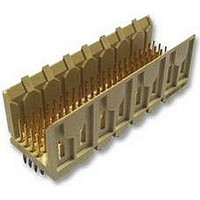
Description
Conn Backplane PIN 48 POS 2mm Press Fit ST Thru-Hole
Manufacturer
TE Connectivity
Type
Backplaner
Series
Z-PACKr
Specifications of 5536504-2
Pitch
2 mm
Number Of Rows
4
Number Of Contacts
48
Termination Method
Press Fit
Mounting
Through Hole
Contact Plating
Gold Over Nickel
Pitch (mm)
2mm
Gender
Pin
Body Orientation
Straight
Number Of Contact Rows
4
Mounting Style
Through Hole
Voltage Rating Max
30VAC
Contact Material
Phosphor Bronze
Housing Color
Natural
Housing Material
Liquid Cryst Polymer
Product Height (mm)
17mm
Product Depth (mm)
15.8mm
Product Length (mm)
23.88mm
Connector Type
Backplane
Row Pitch
2mm
Pitch Spacing
2mm
No. Of Contacts
48
Contact Termination
Press Fit
No. Of Rows
4
Contact
RoHS Compliant
Number Of Positions / Contacts
48
Mounting Angle
Vertical
Termination Style
Pin
Product Type
Connector
Pcb Mounting Orientation
Vertical
Post Type
Press-Fit
Module Type
Signal
Mating Post Length (mm [in])
6.50 [0.256]
Press-fit Post Style
Compliant Pin
Pin Header Width (mm [in])
16.00 [0.622]
Voltage Rating (vac)
30
Termination Post Length (mm [in])
4.25 [0.167]
Number Of Signal Positions
48
Sequencing
No
Post Plating
Tin
Centerline, Matrix (mm [in])
2.00 x 2.00 [.079 x .079]
Contact Type
Pin
Contact Base Material
Phosphor Bronze
Contact Plating, Mating Area, Material
Gold (30)
Connector Style
Plug
Rohs/elv Compliance
RoHS compliant, ELV compliant
Lead Free Solder Processes
Not relevant for lead free process
Rohs/elv Compliance History
Always was RoHS compliant
Applies To
Printed Circuit Board
Application
Fixed-Board
Lead Free Status / RoHS Status
Compliant
Lead Free Status / RoHS Status
Compliant


5. TOOLING
TE has existing tooling and tooling concepts for applying these connectors. Part numbers of available tools and
the applicable instructional material for each is provided in Figure 12.
Rev E
NOTE
S
S
S
S
S
S
i
Robotic Equipment
Robotic equipment for placement of connectors on a pc board must have a true position accuracy of
0.13 mm to ensure proper location and insertion of the contact pins. This includes gripper and fixture
tolerances as well as equipment repeatability. It must use the connector datum surface to ensure reliable
connector placement. If you need assistance in setting up prototype or production line equipment,
contact Tooling Engineering through your local TE Representative or call the Tooling Assistance Center
number at the bottom of page 1.
Seating Tool
Seating tools are designed to push evenly on the shoulders of the vertical pin contact and force the
compliant pins into the pc board. See Figure 1.
Push Bar
Commercially available bar stock with a flat surface large enough to cover the top surface of right--angle
connectors and capable of exerting 67 N per pin can be used as a push bar to seat the compliant pin
and solder tine connectors onto the pc board. The same type tooling can be used to remove damaged
right--angle connectors from a pc board by pressing evenly on the compliant end of the contacts.
PC Board Support
A pc board support must be used to prevent bowing of the pc board during insertion of the connectors. It
should have a flat surface with holes or a channel large enough to receive the pins during installation.
Housing Support
A housing support with sides and ends as close as possible to the receptacle housing is recommended
for removing damaged receptacle connectors from pc boards.
Repair Tool
A repair tool kit consisting of a spring--loaded impact tool handle assembly, a removal tip, and a
replacement tip is available for removing damaged compliant pin contacts and replacing them with new
ones. The housing must be supported and the contact must be free to back out of housing with a
suitable housing support that will not damage housing.
The tooling referenced in Figure 12 may be used for both compliant pin and solder type connectors.
PC Board Support Fixture
(Customer Supplied)
PC Board Support Fixture
679980- - 1 or - - 2 With Bottom
Support Anvil 679977- - 1 or - - 2
(408- - 4038)
Typical Seating
Tool (See Table)
Figure 12 (cont’d)
H- - Frame Power
Unit 803880- - 6
114- 1075
13 of 15
Related parts for 5536504-2
Image
Part Number
Description
Manufacturer
Datasheet
Request
R

Part Number:
Description:
Printers THERMAL PRINTER HS-SLEEVE MARKER
Manufacturer:
TE Connectivity


Part Number:
Description:
High Speed / Modular Connectors 30P HEADER ASSY
Manufacturer:
TE Connectivity
Datasheet:

Part Number:
Description:
High Speed / Modular Connectors REC 6X005P R/A LT B-PLANE HS3
Manufacturer:
TE Connectivity
Datasheet:

Part Number:
Description:
High Speed / Modular Connectors 2MM HM RCPT 50P R/A AU
Manufacturer:
TE Connectivity
Datasheet:

Part Number:
Description:
High Speed / Modular Connectors 2MM HM RCPT 50P R/A AU
Manufacturer:
TE Connectivity
Datasheet:


Part Number:
Description:
Manufacturer:
TE Connectivity
Datasheet:


Part Number:
Description:
Manufacturer:
TE Connectivity
Datasheet:

Part Number:
Description:
Manufacturer:
TE Connectivity
Datasheet:

Part Number:
Description:
Manufacturer:
TE Connectivity
Datasheet: