5536504-2 TE Connectivity, 5536504-2 Datasheet - Page 5
5536504-2
Manufacturer Part Number
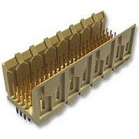
5536504-2
Description
Conn Backplane PIN 48 POS 2mm Press Fit ST Thru-Hole
Manufacturer
TE Connectivity
Type
Backplaner
Series
Z-PACKr
Specifications of 5536504-2
Pitch
2 mm
Number Of Rows
4
Number Of Contacts
48
Termination Method
Press Fit
Mounting
Through Hole
Contact Plating
Gold Over Nickel
Pitch (mm)
2mm
Gender
Pin
Body Orientation
Straight
Number Of Contact Rows
4
Mounting Style
Through Hole
Voltage Rating Max
30VAC
Contact Material
Phosphor Bronze
Housing Color
Natural
Housing Material
Liquid Cryst Polymer
Product Height (mm)
17mm
Product Depth (mm)
15.8mm
Product Length (mm)
23.88mm
Connector Type
Backplane
Row Pitch
2mm
Pitch Spacing
2mm
No. Of Contacts
48
Contact Termination
Press Fit
No. Of Rows
4
Contact
RoHS Compliant
Number Of Positions / Contacts
48
Mounting Angle
Vertical
Termination Style
Pin
Product Type
Connector
Pcb Mounting Orientation
Vertical
Post Type
Press-Fit
Module Type
Signal
Mating Post Length (mm [in])
6.50 [0.256]
Press-fit Post Style
Compliant Pin
Pin Header Width (mm [in])
16.00 [0.622]
Voltage Rating (vac)
30
Termination Post Length (mm [in])
4.25 [0.167]
Number Of Signal Positions
48
Sequencing
No
Post Plating
Tin
Centerline, Matrix (mm [in])
2.00 x 2.00 [.079 x .079]
Contact Type
Pin
Contact Base Material
Phosphor Bronze
Contact Plating, Mating Area, Material
Gold (30)
Connector Style
Plug
Rohs/elv Compliance
RoHS compliant, ELV compliant
Lead Free Solder Processes
Not relevant for lead free process
Rohs/elv Compliance History
Always was RoHS compliant
Applies To
Printed Circuit Board
Application
Fixed-Board
Lead Free Status / RoHS Status
Compliant
Lead Free Status / RoHS Status
Compliant


3.3. Alignment
Proper alignment is essential to ensure full engagement of mating connectors, and to ensure that contacts are
not bent or otherwise damaged during mating and unmating. For tolerance limitations, see Figure 4.
NOTE: 4- - row shown, 5- - row is the same for dimensioning purposes.
2.5
Rev E
NOTE: 4- - row shown, 5- - row is the same for dimensioning purposes.
C. Guides
The pin headers have alignment slots with a guide--in that helps position the pin and socket contacts prior
to engagement of the circuits. See Figure 1.
D. End- to- End Placement
The end contacts in the pin header and receptacle are one half the contact spacing distance from the ends
of the housing. This design feature makes it possible to mount connectors end--to--end while maintaining
the 2 mm grid pattern. When making this type of application, note that the contacts in the pin header are
closer to one side of the housing to allow space for the mating pc board. The contacts and board slots
must be aligned with each other when mating with a continuous pc board connector. Connectors can be
mounted end--to--end within the specified dimension. See Figure 3.
Pin Header Connectors
2.5
2 mm
1 mm
1.5
(2 Places)
PC Board (Typ)
9.2 (Min)
Figure 3
Figure 4
Joining
Ends
Pin
Header
Receptacle
Receptacle Connectors
+2_
1 mm
2 mm
114- 1075
+2_
5 of 15
Related parts for 5536504-2
Image
Part Number
Description
Manufacturer
Datasheet
Request
R

Part Number:
Description:
Printers THERMAL PRINTER HS-SLEEVE MARKER
Manufacturer:
TE Connectivity


Part Number:
Description:
High Speed / Modular Connectors 30P HEADER ASSY
Manufacturer:
TE Connectivity
Datasheet:

Part Number:
Description:
High Speed / Modular Connectors REC 6X005P R/A LT B-PLANE HS3
Manufacturer:
TE Connectivity
Datasheet:

Part Number:
Description:
High Speed / Modular Connectors 2MM HM RCPT 50P R/A AU
Manufacturer:
TE Connectivity
Datasheet:

Part Number:
Description:
High Speed / Modular Connectors 2MM HM RCPT 50P R/A AU
Manufacturer:
TE Connectivity
Datasheet:


Part Number:
Description:
Manufacturer:
TE Connectivity
Datasheet:


Part Number:
Description:
Manufacturer:
TE Connectivity
Datasheet:

Part Number:
Description:
Manufacturer:
TE Connectivity
Datasheet:

Part Number:
Description:
Manufacturer:
TE Connectivity
Datasheet: