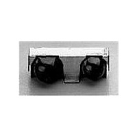
HSDL-3612-007 Lite-On Electronics, HSDL-3612-007 Datasheet - Page 7

HSDL-3612-007
Manufacturer Part Number
HSDL-3612-007
Description
Infrared Transceivers IR Transceiver 115.2Kb/s
Manufacturer
Lite-On Electronics
Type
TX/RXr
Datasheet
1.HSDL-3612-007.pdf
(25 pages)
Specifications of HSDL-3612-007
Pulse Width
1.6/4us
Led Supply Voltage
-0.5 to 7V
Dimensions
12.2x5.1x4
Peak Wavelength
875/880nm
Angle Of Half Sensitivity
60/30°
Communication Distance
150
Package Type
Ultra Small Profile
Fall Time
40/25ns
Rise Time
40/25ns
Operating Supply Voltage (typ)
3.3/5V
Operating Supply Voltage (min)
2.7V
Operating Supply Voltage (max)
5.25V
Mounting
Surface Mount
Pin Count
10
Operating Temp Range
-20C to 70C
Operating Temperature Classification
Commercial
Data Rate
115.2Kbps
Wavelength
875 nm, 880 nm
Continual Data Transmission
115.2 Kbit/s
Transmission Distance
1.5 m
Radiant Intensity
120 mW/sr
Half Intensity Angle Degrees
30 deg to 60 deg
Maximum Rise Time
40 ns, 25 ns
Maximum Fall Time
40 ns, 25 ns
Maximum Forward Current
165 mA
Operating Voltage
2.7 V to 5.25 V
Maximum Operating Temperature
+ 70 C
Minimum Operating Temperature
- 20 C
Idle Current, Typ @ 25° C
2.5mA
Link Range, Low Power
1m
Operating Temperature
-20°C ~ 70°C
Orientation
Side View
Shutdown
*
Size
12.2mm x 5.1mm x 4mm
Standards
IrPHY 1.0
Supply Voltage
2.7 V ~ 5.25 V
Lead Free Status / RoHS Status
Compliant
Lead Free Status / RoHS Status
Lead free / RoHS Compliant, Compliant
7
Electrical & Optical Specifications
Specifications hold over the Recommended Operating Conditions unless otherwise noted. Unspecified test condi-
tions can be anywhere in their operating range. All typical values are at 25°C and 3.3 V unless otherwise noted.
Receiver
Receiver
Data Output
Voltage
Logic High Receiver Input
Irradiance
Logic Low Receiver Input
Receiver Peak Sensitivity
Wavelength
Receiver SIR Pulse Width
Receiver Latency Time
Receiver Rise/Fall Times
Receiver Wake Up Time
Notes:
7. Logic Low is a pulsed response. The condition is maintained for duration dependent on pattern and strength of the incident intensity.
8. An in-band optical signal is a pulse/sequence where the peak wavelength, lp, is defined as 850 ≤ lp ≤ 900 nm, and the pulse characteristics
9. For in-band signals ≤ 115.2 kb/s where 3.6 µW/cm
10. Wake Up Time is the time between the transition from a shutdown state to an active state and the time when the receiver is active and
Irradiance
are compliant with the IrDA Serial Infrared Physical Layer Link Specification.
ready to receive infrared signals.
Parameter
Logic Low
Logic High
Viewing Angle 2θ
[7]
Symbol
V
V
EI
EI
λ
tpw (SIR)
t
t
t
L
r/f
W
P
OL
OH
H
L
1/2
(RXD)
2
≤ EI ≤ 500 mW/cm
Min.
0
V
30
0.0036
1
CC
– 0.2 -
2
.
Typ.
-
880
20
25
Max.
0.4
V
500
0.3
4.0
50
100
CC
Unit
V
V
°
mW/cm
µW/cm
nm
µs
µs
ns
µs
2
2
I
EI ≥ 3.6 µW/cm
θ
I
EI ≤ 0.3 µW/cm
θ
For in-band signals ≤
115.2 kb/s
For in-band signals
θ
[10]
OL
OH
1/2
1/2
1/2
= 1.0 mA,
= –20 µA,
≤ 15°
≤ 15°
≤ 15°
Conditions
[9]
[8]
, C
L
= 10 pF
2
2
,
,
[8]


