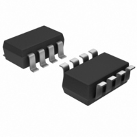
AD7999YRJZ-1500RL7 Analog Devices Inc, AD7999YRJZ-1500RL7 Datasheet - Page 25

AD7999YRJZ-1500RL7
Manufacturer Part Number
AD7999YRJZ-1500RL7
Description
IC ADC 8BIT 4CH SAR I2C SOT23-8
Manufacturer
Analog Devices Inc
Specifications of AD7999YRJZ-1500RL7
Data Interface
I²C, Serial
Design Resources
Using AD8599 as an Ultralow Distortion Driver for the AD7999 (CN0045)
Number Of Bits
8
Sampling Rate (per Second)
1M
Number Of Converters
1
Power Dissipation (max)
4.68mW
Voltage Supply Source
Single Supply
Operating Temperature
-40°C ~ 125°C
Mounting Type
Surface Mount
Package / Case
SOT-23-8
Resolution (bits)
8bit
Input Channel Type
Single Ended
Supply Voltage Range - Analogue
2.7V To 5.5V
Supply Current
850µA
No. Of Pins
8
Operating Temperature Range
-40°C To
Sampling Rate
140kSPS
Digital Ic Case Style
SOT-23
Rohs Compliant
Yes
Lead Free Status / RoHS Status
Lead free / RoHS Compliant
Other names
AD7999YRJZ-1500RL7TR
Available stocks
Company
Part Number
Manufacturer
Quantity
Price
Company:
Part Number:
AD7999YRJZ-1500RL7
Manufacturer:
ADI
Quantity:
3 000
Part Number:
AD7999YRJZ-1500RL7
Manufacturer:
ADI/亚德诺
Quantity:
20 000
PLACING THE AD7991/AD7995/AD7999 INTO HIGH SPEED MODE
High speed mode communication commences after the master
addresses all devices connected to the bus with the master code,
00001XXX, to indicate that a high speed mode transfer is to
begin. No device connected to the bus is allowed to acknowledge
the high speed master code; therefore, the code is followed by a
NO ACK (see Figure 26). The master must then issue a repeated
start, followed by the device address and an R/ W bit. The selected
device then acknowledges its address.
SDA
SCL
SDA
SCL
START BY
START BY
MASTER
MASTER
0
1
0
1
Figure 27. Reading Two Bytes of Data from the Conversion Result Register in High Speed Mode for AD7991
1
0
SERIAL BUS ADDRESS BYTE
HS MODE MASTER CODE
0
0
FAST MODE
1
FRAME 1
0
0
1
SCL (CONTINUED)
SDA (CONTINUED)
0
X
Figure 26. Placing the Part into High Speed Mode
A0
X
CLOCK HIGH TIME = 2µs
R/W
X
Rev. B | Page 25 of 28
NO ACK
ACK BY
ADC
9
9
Sr
1
D7
1
0
1
All devices continue to operate in high speed mode until the
master issues a stop condition. When the stop condition is
issued, the devices return to fast mode.
To guarantee performance above f
perform clock stretching—that is, the clock must be held high—for
2 μs after the ninth clock rising edge (see Figure 27). Therefore,
the clock must be held high for 2 μs after the device starts to power
up (see the Reading from the AD7991/AD7995/AD7999 section).
0
D6
LEAST SIGNIFICANT DATA BYTE FROM ADC
0
MOST SIGNIFICANT DATA BYTE FROM ADC
CH
1
D5
SERIAL BUS ADDRESS BYTE
ID1
HIGH SPEED MODE
0
CH
D4
ID0
FRAME 3
FRAME 2
1
D11
D3
0
D10
D2
AD7991/AD7995/AD7999
0
D1
D9
A0
SCL
D8
D0
ACK BY
NO ACK BY
ADC
MASTER
= 1.7 MHz, the user must
MASTER
ACK BY
9
9
9
STOP BY
MASTER


