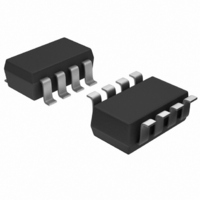
AD7999YRJZ-1500RL7 Analog Devices Inc, AD7999YRJZ-1500RL7 Datasheet - Page 26

AD7999YRJZ-1500RL7
Manufacturer Part Number
AD7999YRJZ-1500RL7
Description
IC ADC 8BIT 4CH SAR I2C SOT23-8
Manufacturer
Analog Devices Inc
Specifications of AD7999YRJZ-1500RL7
Data Interface
I²C, Serial
Design Resources
Using AD8599 as an Ultralow Distortion Driver for the AD7999 (CN0045)
Number Of Bits
8
Sampling Rate (per Second)
1M
Number Of Converters
1
Power Dissipation (max)
4.68mW
Voltage Supply Source
Single Supply
Operating Temperature
-40°C ~ 125°C
Mounting Type
Surface Mount
Package / Case
SOT-23-8
Resolution (bits)
8bit
Input Channel Type
Single Ended
Supply Voltage Range - Analogue
2.7V To 5.5V
Supply Current
850µA
No. Of Pins
8
Operating Temperature Range
-40°C To
Sampling Rate
140kSPS
Digital Ic Case Style
SOT-23
Rohs Compliant
Yes
Lead Free Status / RoHS Status
Lead free / RoHS Compliant
Other names
AD7999YRJZ-1500RL7TR
Available stocks
Company
Part Number
Manufacturer
Quantity
Price
Company:
Part Number:
AD7999YRJZ-1500RL7
Manufacturer:
ADI
Quantity:
3 000
Part Number:
AD7999YRJZ-1500RL7
Manufacturer:
ADI/亚德诺
Quantity:
20 000
AD7991/AD7995/AD7999
MODE OF OPERATION
The AD7991/AD7995/AD7999 powers up in shutdown mode.
After the master addresses the AD7991/AD7995/AD7999 with
the correct I
response, the AD7991/AD7995/AD7999 power up.
During this wake up time, the AD7991/AD7995/AD7999 exit
shutdown mode and begin to acquire the analog input (acquisition
phase). By default, all channels are selected. Which channels
are converted depends on the status of the channel bits in the
configuration register.
When the read address is acknowledged, the ADC outputs two
bytes of conversion data. The first byte contains four status bits
and the four MSBs of the conversion result. The status bits
contain two leading 0s and two channel-identifier bits. After
this first byte, the AD7991/AD7995/AD7999 outputs the
2
SDA
SCL
C address, the ADC acknowledges the address. In
Sr
1
7-BIT ADDRESS
Figure 28. Mode of Operation, Single-Channel Conversion
R
ACK. BY
ADC
A
9
1
Rev. B | Page 26 of 28
FIRST DATA BYTE
(MSB)
second byte of the conversion result. For the AD7991, this
second byte contains the lower eight bits of conversion data. For
the AD7995, this second byte contains six bits of conversion
data plus two trailing 0s. For the AD7999, this second byte
contains four bits of conversion data and four trailing 0s.
The master then sends a NO ACK to the AD7991/AD7995/
AD7999, as long as no further reads are required. If the master
instead sends an ACK to the AD7991/AD7995/AD7999, the
ADC powers up and completes another conversion. When
more than one channel bit has been set in the configuration
register, this conversion is performed on the second channel in
the selected sequence. If only one channel is selected, the ADC
converts again on the selected channel.
MASTER
ACK. BY
A
9
SECOND DATA BYTE
(LSB)
NO ACK. BY
MASTER
A
9
Sr/P


