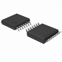
BU2507FV-E2 Rohm Semiconductor, BU2507FV-E2 Datasheet - Page 7

BU2507FV-E2
Manufacturer Part Number
BU2507FV-E2
Description
IC DAC 10BIT 6-CHAN SSOP-B14
Manufacturer
Rohm Semiconductor
Specifications of BU2507FV-E2
Data Interface
Serial
Settling Time
7µs
Number Of Bits
10
Number Of Converters
6
Voltage Supply Source
Single Supply
Operating Temperature
-30°C ~ 85°C
Mounting Type
Surface Mount
Package / Case
14-SSOP
Resolution (bits)
10bit
Sampling Rate
10MSPS
Input Channel Type
Serial
Supply Voltage Range - Analogue
4.5V To 5.5V
Supply Current
850µA
Digital Ic Case Style
SSOP
No. Of
RoHS Compliant
Resolution
10 bit
Interface Type
Serial (3-Wire)
Supply Voltage (max)
5.5 V
Supply Voltage (min)
4.5 V
Maximum Operating Temperature
+ 85 C
Mounting Style
SMD/SMT
Minimum Operating Temperature
- 30 C
Lead Free Status / RoHS Status
Lead free / RoHS Compliant
Power Dissipation (max)
-
Lead Free Status / Rohs Status
Lead free / RoHS Compliant
Other names
BU2507FV-E2
BU2507FV-E2TR
BU2507FV-E2TR
Available stocks
Company
Part Number
Manufacturer
Quantity
Price
Company:
Part Number:
BU2507FV-E2
Manufacturer:
RohmSemic
Quantity:
4 554
Part Number:
BU2507FV-E2
Manufacturer:
ROHM/罗姆
Quantity:
20 000
●Standard Example Application Circuit
●Notes for use
© 2009 ROHM Co., Ltd. All rights reserved.
BU2508FV,BU2507FV
www.rohm.com
(1) The electrical characteristic and data on graphs for this datasheet, are typically evaluated value, and not guaranteed.
(2) We suppose that application circuits are recommendable, but please make sufficient check for characteristics with the
(3) About absolute maximum ratings
(4) GND voltage
(5) Thermal design
(6) About terminals short and wrong mounting
(7) About operation in strong electromagnetic field
(8) Place a bypass capacitor as close as possible between each power supply terminal and ground in order to prevent
(9) A capacitor should be inserted between the analog output and ground in order to eliminate noise.
actual application. In case that value of external component for this IC is changed, please check characteristic, not only
static but also transient.
If operation condition is over the absolute maximum ratings, supply voltage or other operation range, IC will be broken.
Please don't apply any voltage or temperature over the absolute maximum ratings. If application have possibilities of
become over the absolute maximum ratings, please take safety measures by using fuse and so on. Not to over absolute
maximum ratings of IC.
Please keep GND voltage lowest of any other terminal of this IC. Please confirm other terminal voltages is not lower
than GND.
Please making a thermal design that allows for a sufficient margin in light of the power dissipation in actual operating
condition.
Please pay full attention to the IC direction and displacement when mounting IC on PCB. If you assemble them by
mistake and electrify it, IC might be destroyed. And it is happen to short among IC terminals or terminals and power
supply, by foreign substance.
If you use it in strong electromagnetic field, please evaluate fully as there is a possibility of malfunction.
deterioration of the D/A conversion accuracy due to ripple and noise signals from power supply or GND.
A capacitance up to 100pF is recommended (including the capacitance of the wire).
C ontroller
V
V
R eset
LD
C LK
D I
refH
refL
G N D
V C C
7/8
A O 1
A O 2
A O 3
A O 6
C H 1
C H 2
C H 3
C H 6
Technical Note
2011.04 - Rev.B


