AD660SQ Analog Devices Inc, AD660SQ Datasheet - Page 17
AD660SQ
Manufacturer Part Number
AD660SQ
Description
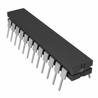
IC DAC 16BIT MONO W/VREF 24-CDIP
Manufacturer
Analog Devices Inc
Series
DACPORT®r
Datasheet
1.AD660ARZ.pdf
(20 pages)
Specifications of AD660SQ
Rohs Status
RoHS non-compliant
Settling Time
6µs
Number Of Bits
16
Data Interface
Serial
Number Of Converters
1
Voltage Supply Source
Analog and Digital, Dual ±
Power Dissipation (max)
625mW
Operating Temperature
-55°C ~ 125°C
Mounting Type
Through Hole
Package / Case
24-CDIP (0.300", 7.62mm)
Available stocks
Company
Part Number
Manufacturer
Quantity
Price


BOARD LAYOUT
Designing with high resolution data converters requires careful
attention to board layout. Trace impedance is the first issue. A
306 μA current through a 0.5 Ω trace develops a voltage drop of
153 μV, which is 1 LSB at the 16-bit level for a 10 V full-scale
span. In addition to ground drops, inductive and capacitive
coupling need to be considered, especially when high accuracy
analog signals share the same board with digital signals. Finally,
power supplies need to be decoupled to filter out ac noise.
Analog and digital signals should not share a common path.
Each signal should have an appropriate analog or digital return
routed close to it. Using this approach, signal loops enclose a
small area, minimizing the inductive coupling of noise. Wide
PC tracks, large gauge wire, and ground planes are highly
recommended to provide low impedance signal paths. Separate
analog and digital ground planes should also be used, with a
single interconnection point to minimize ground loops. Analog
signals should be routed as far as possible from digital signals
and should cross them at right angles.
One feature that the AD660 incorporates to help the user layout
is that the analog pins (+V
BIPOLAR OFFSET, V
isolate analog signals from digital signals.
SUPPLY DECOUPLING
The AD660 power supplies should be well filtered, well regulated,
and free from high frequency noise. Switching power supplies
are not recommended due to their tendency to generate spikes,
which can induce noise in the analog system.
Decoupling capacitors should be used in very close layout
proximity between all power supply pins and ground. A 10 μF
OUT
and AGND) are adjacent to help
CC
, −V
EE
, REF OUT, REF IN, SPAN/
Rev. B | Page 17 of 20
tantalum capacitor in parallel with a 0.1 μF ceramic capacitor
provides adequate decoupling. V
to analog ground, while V
An effort should be made to minimize the trace length between
the capacitor leads and the respective converter power supply
and common pins. The circuit layout should attempt to locate
the AD660, associated analog circuitry, and interconnections as
far as possible from logic circuitry. A solid analog ground plane
around the AD660 will isolate large switching ground currents.
For these reasons, the use of wire wrap circuit construction is
not recommended; careful printed circuit construction is
preferred.
GROUNDING
The AD660 has two ground pins, designated analog ground
(AGND) and digital ground (DGND.) The analog ground pin is
the high quality ground reference point for the device. Any
external loads on the output of the AD660 should be returned
to analog ground. If an external reference is used, this should
also be returned to the analog ground.
If a single AD660 is used with separate analog and digital ground
planes, connect the analog ground plane to AGND and the digital
ground plane to DGND keeping lead lengths as short as possible.
Then connect AGND and DGND together at the AD660. If
multiple AD660 devices are used or the AD660 shares analog
supplies with other components, connect the analog and digital
returns together once at the power supplies rather than at each
chip. This single interconnection of grounds prevents large
ground loops and consequently prevents digital currents from
flowing through the analog ground.
LL
should be decoupled to digital ground.
CC
and V
EE
should be bypassed
AD660
Related parts for AD660SQ
Image
Part Number
Description
Manufacturer
Datasheet
Request
R

Part Number:
Description:
±1.7g Dual-Axis IMEMS Accelerometer Evaluation Board
Manufacturer:
Analog Devices Inc
Datasheet:

Part Number:
Description:
Inertial Sensor Evaluation System
Manufacturer:
Analog Devices Inc
Datasheet:
Part Number:
Description:
Manufacturer:
Analog Devices Inc
Datasheet:
Part Number:
Description:
Manufacturer:
Analog Devices Inc
Datasheet:
Part Number:
Description:
Manufacturer:
Analog Devices Inc
Datasheet:
Part Number:
Description:
Manufacturer:
Analog Devices Inc
Datasheet:
Part Number:
Description:
Manufacturer:
Analog Devices Inc
Datasheet:
Part Number:
Description:
Manufacturer:
Analog Devices Inc
Datasheet:
Part Number:
Description:
Manufacturer:
Analog Devices Inc
Datasheet:
Part Number:
Description:
Manufacturer:
Analog Devices Inc
Datasheet:
Part Number:
Description:
Manufacturer:
Analog Devices Inc
Datasheet:
Part Number:
Description:
Manufacturer:
Analog Devices Inc
Datasheet:
Part Number:
Description:
Manufacturer:
Analog Devices Inc
Datasheet: