MSC8122TVT6400V Freescale Semiconductor, MSC8122TVT6400V Datasheet - Page 18
MSC8122TVT6400V
Manufacturer Part Number
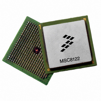
MSC8122TVT6400V
Description
IC DSP QUAD 16B 400MHZ 431FCPBGA
Manufacturer
Freescale Semiconductor
Series
MSC81xx StarCorer
Type
SC140 Corer
Datasheets
1.MSC8122TVT6400V.pdf
(48 pages)
2.MSC8122TVT6400V.pdf
(2 pages)
3.MSC8122TVT6400V.pdf
(8 pages)
Specifications of MSC8122TVT6400V
Interface
DSI, Ethernet, RS-232
Clock Rate
400MHz
Non-volatile Memory
External
On-chip Ram
1.436MB
Voltage - I/o
3.30V
Voltage - Core
1.10V
Operating Temperature
0°C ~ 90°C
Mounting Type
Surface Mount
Package / Case
431-FCPBGA
For Use With
MSC8122ADSE - KIT ADVANCED DEV SYSTEM 8122
Lead Free Status / RoHS Status
Lead free / RoHS Compliant
Available stocks
Company
Part Number
Manufacturer
Quantity
Price
Company:

Part Number:
MSC8122TVT6400V
Manufacturer:
Freescale
Quantity:
1 400
Company:
Part Number:
MSC8122TVT6400V
Manufacturer:
Freescale Semiconductor
Quantity:
10 000


Electrical Characteristics
In all cases, the power-up sequence must follow the guidelines shown in Figure 8.
The following rules apply:
2.5.3
The following sections include a description of clock signal characteristics. Table 7 shows the maximum frequency values for
internal (Core, Reference, Bus, and DSI) and external (
frequency values are not exceeded.
18
Core frequency
Reference frequency (REFCLK)
Internal bus frequency (BLCK)
DSI clock frequency (HCLKIN)
•
•
External clock frequency (CLKIN or CLKOUT)
CLKIN frequency
BCLK frequency
Reference clock (REFCLK) frequency
Output clock (CLKOUT) frequency
SC140 core clock frequency
Note:
Core frequency = 300 MHz
Core frequency = 400/500 MHz
1.
2.
3.3 V
1.2 V
During time interval A,
The duration of interval A should be kept below 10 ms.
The duration of timing interval B should be kept as small as possible and less than 10 ms.
V
The rise and fall time of external clocks should be 3 ns maximum
Characteristics
Clock and Timing Signals
Characteristic
Figure 8. Power-Up Sequence for V
MSC8122 Quad Digital Signal Processor Data Sheet, Rev. 16
V
A
DDH
should always be equal to or less than the
Symbol
F
F
F
F
Table 7. Maximum Frequencies
F
CLKOUT
REFCLK
CLKIN
CORE
BCLK
Table 8. Clock Frequencies
B
CLKIN
300 MHz Device
Min
200
20
40
40
40
and
V
CLKOUT
DD
Max
100
100
100
100
300
/V
DDH
V
CCSYN
HCLKIN ≤ (min{100 MHz, CLKOUT})
HCLKIN ≤ (min{70 MHz, CLKOUT})
DDH
) clocks. The user must ensure that maximum
and V
(IO)
Maximum in MHz
V
400 MHz Device
Min
200
DD
20
40
40
40
DD
300/400/500
100/133/166
100/133/166
100/133/166
/
V
/V
CCSYN
CCSYN
133.3
133.3
133.3
133.3
Max
voltage level.
400
Freescale Semiconductor
500 MHz Device
Min
200
20
40
40
40
t (time)
166.7
166.7
166.7
166.7
Max
500
Related parts for MSC8122TVT6400V
Image
Part Number
Description
Manufacturer
Datasheet
Request
R

Part Number:
Description:
Manufacturer:
Freescale Semiconductor, Inc
Datasheet:
Part Number:
Description:
Manufacturer:
Freescale Semiconductor, Inc
Datasheet:
Part Number:
Description:
Manufacturer:
Freescale Semiconductor, Inc
Datasheet:
Part Number:
Description:
Manufacturer:
Freescale Semiconductor, Inc
Datasheet:
Part Number:
Description:
Manufacturer:
Freescale Semiconductor, Inc
Datasheet:
Part Number:
Description:
Manufacturer:
Freescale Semiconductor, Inc
Datasheet:
Part Number:
Description:
Manufacturer:
Freescale Semiconductor, Inc
Datasheet:
Part Number:
Description:
Manufacturer:
Freescale Semiconductor, Inc
Datasheet:
Part Number:
Description:
Manufacturer:
Freescale Semiconductor, Inc
Datasheet:
Part Number:
Description:
Manufacturer:
Freescale Semiconductor, Inc
Datasheet:
Part Number:
Description:
Manufacturer:
Freescale Semiconductor, Inc
Datasheet:
Part Number:
Description:
Manufacturer:
Freescale Semiconductor, Inc
Datasheet:
Part Number:
Description:
Manufacturer:
Freescale Semiconductor, Inc
Datasheet:
Part Number:
Description:
Manufacturer:
Freescale Semiconductor, Inc
Datasheet:
Part Number:
Description:
Manufacturer:
Freescale Semiconductor, Inc
Datasheet: