MSC8122TVT6400V Freescale Semiconductor, MSC8122TVT6400V Datasheet - Page 43
MSC8122TVT6400V
Manufacturer Part Number
MSC8122TVT6400V
Description
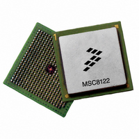
IC DSP QUAD 16B 400MHZ 431FCPBGA
Manufacturer
Freescale Semiconductor
Series
MSC81xx StarCorer
Type
SC140 Corer
Datasheets
1.MSC8122TVT6400V.pdf
(48 pages)
2.MSC8122TVT6400V.pdf
(2 pages)
3.MSC8122TVT6400V.pdf
(8 pages)
Specifications of MSC8122TVT6400V
Interface
DSI, Ethernet, RS-232
Clock Rate
400MHz
Non-volatile Memory
External
On-chip Ram
1.436MB
Voltage - I/o
3.30V
Voltage - Core
1.10V
Operating Temperature
0°C ~ 90°C
Mounting Type
Surface Mount
Package / Case
431-FCPBGA
For Use With
MSC8122ADSE - KIT ADVANCED DEV SYSTEM 8122
Lead Free Status / RoHS Status
Lead free / RoHS Compliant
Available stocks
Company
Part Number
Manufacturer
Quantity
Price
Company:

Part Number:
MSC8122TVT6400V
Manufacturer:
Freescale
Quantity:
1 400
Company:
Part Number:
MSC8122TVT6400V
Manufacturer:
Freescale Semiconductor
Quantity:
10 000


3.5
An estimation of the chip-junction temperature
where
The power dissipation values for the MSC8122 are listed in Table 2-3. The ambient temperature for the device is the air
temperature in the immediate vicinity that would cool the device. The junction-to-ambient thermal resistances are JEDEC
standard values that provide a quick and easy estimation of thermal performance. There are two values in common usage: the
value determined on a single layer board and the value obtained on a board with two planes. The value that more closely
approximates a specific application depends on the power dissipated by other components on the printed circuit board (PCB).
The value obtained using a single layer board is appropriate for tightly packed PCB configurations. The value obtained using a
board with internal planes is more appropriate for boards with low power dissipation (less than 0.02 W/cm
convection) and well separated components. Based on an estimation of junction temperature using this technique, determine
whether a more detailed thermal analysis is required. Standard thermal management techniques can be used to maintain the
device thermal junction temperature below its maximum. If T
the power dissipation of the chip. You can verify the junction temperature by measuring the case temperature using a small
diameter thermocouple (40 gauge is recommended) or an infrared temperature sensor on a spot on the device case that is painted
black. The MSC8122 device case surface is too shiny (low emissivity) to yield an accurate infrared temperature measurement.
Use the following equation to determine T
where
Note:
4
Consult a Freescale Semiconductor sales office or authorized distributor to determine product availability and place an order.
Freescale Semiconductor
MSC8122
Part
T
R
P
P
P
T
θ
P
See MSC8102, MSC8122, and MSC8126 Thermal Management Design Guidelines (AN2601/D).
A
D
INT
I/O
JA
D
T
θ
Ordering Information
Flip Chip Plastic Ball Grid Array (FC-PBGA)
JA
= thermocouple (or infrared) temperature on top of the package (°C)
= ambient temperature near the package (°C)
= P
= power dissipation in the package (W)
= thermal characterization parameter (°C/W)
Thermal Considerations
= power dissipated from device on output pins (W)
= I
= junction-to-ambient thermal resistance (°C/W)
INT
DD
+ P
× V
Package Type
I/O
DD
= power dissipation in the package (W)
= internal power dissipation (W)
MSC8122 Quad Digital Signal Processor Data Sheet, Rev. 16
J
:
,
T
T
T
Voltage
J
J
J
Core
,
= T
1.1 V
1.2 V
in °C can be obtained from the following:
= T
A
T
+ (R
+ (θ
Temperature
θ
–40° to 105°C
–40° to 105°C
Operating
JA
J
JA
0° to 90°C
appears to be too high, either lower the ambient temperature or
× P
× P
D
D
)
)
Frequency
(MHz)
Core
300
400
400
500
MSC8122TVT4800V
MSC8122TVT6400V
MSC8122TVT6400
MSC8122VT8000
Lead-Free
Order Number
Ordering Information
2
with natural
MSC8122TMP4800V
MSC8122TMP6400V
MSC8122TMP6400
Lead-Bearing
MSC8122MP8000
Eqn. 1
Eqn. 2
43
Related parts for MSC8122TVT6400V
Image
Part Number
Description
Manufacturer
Datasheet
Request
R

Part Number:
Description:
Manufacturer:
Freescale Semiconductor, Inc
Datasheet:
Part Number:
Description:
Manufacturer:
Freescale Semiconductor, Inc
Datasheet:
Part Number:
Description:
Manufacturer:
Freescale Semiconductor, Inc
Datasheet:
Part Number:
Description:
Manufacturer:
Freescale Semiconductor, Inc
Datasheet:
Part Number:
Description:
Manufacturer:
Freescale Semiconductor, Inc
Datasheet:
Part Number:
Description:
Manufacturer:
Freescale Semiconductor, Inc
Datasheet:
Part Number:
Description:
Manufacturer:
Freescale Semiconductor, Inc
Datasheet:
Part Number:
Description:
Manufacturer:
Freescale Semiconductor, Inc
Datasheet:
Part Number:
Description:
Manufacturer:
Freescale Semiconductor, Inc
Datasheet:
Part Number:
Description:
Manufacturer:
Freescale Semiconductor, Inc
Datasheet:
Part Number:
Description:
Manufacturer:
Freescale Semiconductor, Inc
Datasheet:
Part Number:
Description:
Manufacturer:
Freescale Semiconductor, Inc
Datasheet:
Part Number:
Description:
Manufacturer:
Freescale Semiconductor, Inc
Datasheet:
Part Number:
Description:
Manufacturer:
Freescale Semiconductor, Inc
Datasheet:
Part Number:
Description:
Manufacturer:
Freescale Semiconductor, Inc
Datasheet: