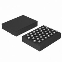
B300W35A102E1G ON Semiconductor, B300W35A102E1G Datasheet - Page 20

B300W35A102E1G
Manufacturer Part Number
B300W35A102E1G
Description
IC PROCESSOR AUDIO 24BIT WLCSP
Manufacturer
ON Semiconductor
Series
BelaSigna® 300r
Type
Floating Pointr
Datasheet
1.B300W35A102XYG.pdf
(31 pages)
Specifications of B300W35A102E1G
Interface
I²C, PCM, SPI, UART
Clock Rate
40MHz
On-chip Ram
110kB
Voltage - I/o
1.0V, 2.0V
Voltage - Core
0.95V
Operating Temperature
-40°C ~ 85°C
Mounting Type
Surface Mount
Package / Case
35-WLCSP
Lead Free Status / RoHS Status
Lead free / RoHS Compliant
Non-volatile Memory
-
Analog Blocks
Input Stage
individual channels. For each channel, one input can be
selected from any of the five possible input sources
(depending on package option) and is then routed to the
Input Dynamic Range Extension (IDRX)
application, it is possible to pair−wise combine the four AD
converters found on BelaSigna 300. This will increase the
dynamic range up to 110 dB. When this technique is used,
the device handles the preamplifier gain configuration based
on the input level and sets it in such a way as to give the
maximum possible dynamic range. This avoids having to
make the design trade−off between sufficient amplification
for low−level signals and avoiding saturation for high−level
signals.
Output Stage
modulator to produce a pulse density modulated (PDM)
output signal. The sampling frequency of the sigma delta
modulator is pre−scaled from the system clock.
directly drive an output transducer without the need for a
The analog audio input stage is comprised of four
To increase the input dynamic range for a particular
The output stage includes a 3
The low−impedance output driver can also be used to
AI3*
AI0
AI1
AI2
AI4
* Not available on WLCSP option
M
U
M
U
X
X
rd
−order sigma−delta
Channel 0
Channel 1
Channel 2
Channel 3
Figure 8. Input Stage
http://onsemi.com
20
Preamp
Preamp
Preamp
Preamp
Preamp
Preamp
Preamp
Preamp
input of the programmable preamplifier that can be
configured for bypass or gain values of 12 to 30 dB (3 dB
steps). The input stage is shown in Figure 8.
configured for any one or more channels. This is useful in
beam−forming applications.
separate power amplifier or can be connected to another
Digital Mic input on another system. The output stage is
shown in Figure 9.
decreases the impedance of the output stage, thus permitting
higher possible acoustic output levels. To use this feature,
RCVR_HP+ should be connected to RCVR+, and
RCVR_HP− should be connected to RCVR−, you must
combine the synchronized output signals externally to
BelaSigna 300. Connect both RCVR+ and RCVR_HP+ to
a single terminal on an output transducer, and connect both
RCVR− and RCVR_HP− to the other terminal. An RC filter
might be required based on receiver characteristics. Figure 9
shows the connections for the output driver in high−power
mode.
in Table 2.
A built−in feature allows a sampling delay to be
BelaSigna 300 has an option for high−power mode that
Electrical specifications on the output stage are available
Conversion
and filtering
Conversion
and filtering
Conversion
and filtering
Conversion
and filtering
IOC


