PVZ2A501A01R00 Murata, PVZ2A501A01R00 Datasheet - Page 5
PVZ2A501A01R00
Manufacturer Part Number
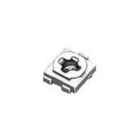
PVZ2A501A01R00
Description
Trimmer Resistors - SMD 500 OHM SMD 2MM
Manufacturer
Murata
Datasheets
1.PVM4A501D01R00.pdf
(1 pages)
2.PVZ2A102A01R00.pdf
(6 pages)
3.PVG5A201C01R00.pdf
(90 pages)
Specifications of PVZ2A501A01R00
Resistance
500 Ohms
Tolerance
30 %
Power Rating
0.1 Watt (1/10 Watt)
Operating Temperature Range
- 25 C to + 85 C
Element Type
Carbon
Number Of Turns
1
Product
Single-Turn Trimmer Potentiometers
Taper
Linear
Termination Style
SMD/SMT
Lead Free Status / Rohs Status
Lead free / RoHS Compliant
Available stocks
Company
Part Number
Manufacturer
Quantity
Price
Company:

Part Number:
PVZ2A501A01R00
Manufacturer:
Murata
Quantity:
7 011
Company:
Part Number:
PVZ2A501A01R00(POZ2AN-1-501N-T
Manufacturer:
MURATA
Quantity:
3 456


9
!Note
!Note
70
1
No.
The tests and measurements shall be conducted under the condition of 15 to 35°C of temperature, 25 to 75% of relative humidity and 86 to 106 kpa of
atmospheric pressure unless otherwise specified. In case when entertained a doubt in judgment obtained from results measured in accordance with the
above mentioned conditions, the tests and measurements shall be conducted under the condition of 25±2°C of temperature and, 45 to 55% of relative
humidity and 86 to 106 kpa of atmospheric pressure.
SMD Open Type and PVM4A_A01 Series Specifications and Test Methods
1
2
3
4
5
6
7
8
Specifications and Test Methods
Total Resistance
Residual Resistanc
Contact Resistance
Humidity Exposure
High Temperature
Exposure
Humidity Load Life
Load Life
Temperature Cycle
• Please read rating and !CAUTION (for storage and operating, rating, soldering and mounting, handling) in this catalog to prevent smoking and/or burning, etc.
• This catalog has only typical specifications because there is no space for detailed specifications. Therefore, please approve our product specification or transact the approval sheet for product specification before ordering.
Please read rating and !CAUTION (for storage and operating, rating, soldering and mounting, handling) in this PDF catalog to prevent smoking and/or burning, etc.
This catalog has only typical specifications. Therefore, you are requested to approve our product specification or to transact the approval sheet for product specificaion before ordering.
Item
Measure total resistance between the resistance element and terminals (terminals #1 and #3) with the contact arm
positioned against a stop. The positioning of the contact arm and terminal shall be the same for subsequent total
resistance measurements on the same device.
Use the test voltage specified in Table-1 for total resistance measurements. This voltage shall be used whenever a
subsequent total resistance measurement is made.
Position the contact arm at the extreme counterclockwise limit of mechanical travel and measure the resistance
between the contact arm and the corresponding end terminal. Then, position the contact arm at the extreme clock-
wise limit of mechanical travel and measure the resistance between the contact arm and the corresponding end ter-
minal. During this test, take suitable precautions to ensure that the rated current of the resistance element is not
exceeded.
Contact resistance variation shall be measured with the measuring circuit shown in below, or its equivalent. The
operating wiper shall be rotated in both directions through 90% of the actual effective-electrical travel for a total of 6
cycles.
The rate of rotation of the operating wiper shall be such that the wiper completes 1 countin determining whether or
not a contact resistance variation is observed at least twice in the same location. The test current shall follow the
value given in Table-2 unless otherwise limited by the power rating.
The wiper contact point shall be pre-setted at about 50% position of effective rotational angle. After that, the poten-
tiometer shall be placed in a chamber at 40±2°C and 90 - 95% without loading for 500±12 hours.
The resistance value shall be measured after keeping the potentiometer in a room for 5±1/6 hours.
The wiper contact point shall be pre-setted at about 50% position of effective rotational angle. After that, the poten-
tiometer shall be placed in a chamber at 70±2°C without loading for 500±12 hours. The resistance value shall be
measured after keeping the potentiometer in a room for 1.5±1/6 hours.
The wiper contact point shall be pre-setted at about 50% position of effective rotational angle. After that, the poten-
tiometer shall be placed in a chamber at 40±2°C and 90 - 95% with loading the 1/2 rated voltage between #1 and #2
terminals, intermittently 1.5 hours ON and 0.5 hours OFF for 1000±12hours.
The resistance value shall be measured after keeping the potentiometer in a room for 5±1/6 hours.
The wiper contact point shall be pre-setted at about 50% position of effective rotational angle. After that, the poten-
tiometer shall be placed in a chamber at 70±2°C (50±2°C for PVZ) with loading the 1/2 rated voltage between #1
and #2 terminals, intermittently 1.5 hours ON and 0.5 hours OFF for 1000±12 hours. The resistance value shall be
measured after keeping the potentiometer in a room for 1.5±1/6 hours.
The wiper contact point shall be pre-setted at about 50% position of effective rotational angle. After that, the poten-
tiometer shall be subjected to Table-3,Table-4 temperature for 5 cycles. The resistance value shall be measured
after keeping the potentiometer in a room for 1.5±10 minutes.
Temp. (°C)
Time (min.)
resistance R (ohm)
Sequence
Total resistance,
100kFR
Nominal (ohm)
Standard total
Table-1 Total resistance test voltage
100FRV1k
100VRF10k
100VR
10kFRV100k
10kVRF100k
10VRV100
1kFRV10k
Table-2 Test current for CRV
-25±3
30±3
1
Table-3 PVZ
10Max.
+25±2
Maximum Test
2
Test Current
100µA Max.
Voltage (V)
10mA Max.
1mA Max.
100.0
10.0
30.0
1.0
3.0
+85±3
30±3
3
10Max.
+25±2
4
Test Methods
Constant Current
Source not to
Exceed Rating of
Unit Being Tested
Time (min.)
Temp. (°C)
Sequence
Rx : Trimmer Potentiometer
Oscilloscope bandwidth :100Hz to 50kHz
Table-4 PVA3/PVS3/PVM4A---A01
Figure-1 CRV measuring circuit
1
-55±3
Proofreaded
Resistence
30±3
1
2
Rx
3
10Max.
+25±2
Continued on the following page.
2
+125±3 +25±2
30±3
3
AC
Amplifier
R50E12.pdf 02.9.5
10Max.
4
Oscilloscope
Related parts for PVZ2A501A01R00
Image
Part Number
Description
Manufacturer
Datasheet
Request
R

Part Number:
Description:
Murata Microblower 20x20 DCDC Driver Board - Samples Only
Manufacturer:
Murata
Part Number:
Description:
357-036-542-201 CARDEDGE 36POS DL .156 BLK LOPRO
Manufacturer:
Murata
Datasheet:
Part Number:
Description:
Manufacturer:
Murata
Datasheet:
Part Number:
Description:
Manufacturer:
Murata
Datasheet:
Part Number:
Description:
Manufacturer:
Murata
Datasheet:
Part Number:
Description:
Manufacturer:
Murata
Datasheet:
Part Number:
Description:
Manufacturer:
Murata
Datasheet:
Part Number:
Description:
Manufacturer:
Murata
Datasheet:
Part Number:
Description:
Manufacturer:
Murata
Datasheet:
Part Number:
Description:
BLM21BD751SN1On-Board Type (DC) EMI Suppression Filters
Manufacturer:
Murata
Datasheet:
Part Number:
Description:
BLM15AG100SN1On-Board Type (DC) EMI Suppression Filters
Manufacturer:
Murata
Datasheet:
Part Number:
Description:
NFE31PT222Z1E9On-Board Type (DC) EMI Suppression Filters
Manufacturer:
Murata
Datasheet:
Part Number:
Description:
Chip Coil
Manufacturer:
Murata
Datasheet:
Part Number:
Description:
Chip Coil
Manufacturer:
Murata
Datasheet: