20-101-1138 Rabbit Semiconductor, 20-101-1138 Datasheet - Page 108
20-101-1138
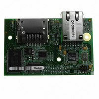
Manufacturer Part Number
20-101-1138
Description
RCM4300 RABBITCORE
Manufacturer
Rabbit Semiconductor
Datasheet
1.20-101-1139.pdf
(124 pages)
Specifications of 20-101-1138
Module/board Type
MPU Core Module
Product
Microcontroller Modules
Data Bus Width
8 bit
Core Processor
Rabbit 4000
Clock Speed
58.98 MHz
Interface Type
Ethernet
Flash
2 MBytes
Timers
10 x 8 bit
Operating Supply Voltage
3.3 V
Board Size
72 mm x 47 mm x 21 mm
For Use With/related Products
RCM4300
Lead Free Status / RoHS Status
Lead free / RoHS Compliant
Other names
316-1141


All signals from the RCM4300 module are available on header J2 of the Prototyping
Board. The remaining ports on the Rabbit 4000 microprocessor are used for RS-232 serial
communication. Table B-2 lists the signals on header J2 and explains how they are used
on the Prototyping Board.
There is a 1.3" × 2" through-hole prototyping space available on the Prototyping Board.
The holes in the prototyping area are spaced at 0.1" (2.5 mm). +3.3 V, +5 V, and GND traces
run along the top edge of the prototyping area for easy access. Small to medium circuits
can be prototyped using point-to-point wiring with 20 to 30 AWG wire between the proto-
typing area, the +3.3 V, +5 V, and GND traces, and the surrounding area where surface-
mount components may be installed. Small holes are provided around the surface-mounted
components that may be installed around the prototyping area.
RabbitCore RCM4300 User’s Manual
* PD0–PD7 (output, high) are available on these pins for the RCM4310.
Table B-2. Use of RCM4300 Signals on the Prototyping Board
22–23
24–25
26–27
28–29
30–31
32–33
35–39
40–47
8–15
Pin
16
17
18
19
20
21
34
48
49
50
1
2
3
4
5
6
/RESET_IN Input to reset generator
/RST_OUT Reset output from reset generator
Pin Name
CONVERT A/D converter CONVERT input (RCM4300 only)
LN0–LN7
PA0–PA7
PB6–PB7
PC0–PC1
PC2–PC3
PC4–PC5
PC6–PC7
PE0–PE1
PE3–PE7
/IOWR
AGND
+3.3 V
/IORD
VREF
GND
PB0
PB1
PB2
PB3
PB4
PB5
PE2
+3.3 V power supply
External read strobe
External write strobe
Output, pulled low
CLKB (shared by serial flash, microSD™ Card, and
A/D converter if equipped)
Programming port CLKA
LED DS2 (normally high/off)
LED DS3 (normally high/off)
Switch S2 (normally open/pulled up)
Switch S3 (normally open/pulled up)
Output, pulled high
Serial Port D (RS-232, header J4) (high)
Serial Port C (high)
Serial Port B (shared by serial flash, microSD™ Card,
and A/D converter if equipped)
Serial Port A (programming port) (high)
Output (high)
Not brought out to Prototyping Board
Output (high)
A/D converter inputs (RCM4300 only)
A/D converter reference voltage (RCM4300 only)
A/D converter ground (RCM4300 only)
Prototyping Board Use
*
*
*
*
108
Related parts for 20-101-1138
Image
Part Number
Description
Manufacturer
Datasheet
Request
R

Part Number:
Description:
COMPUTER SGL-BRD BL2500 29.4MHZ
Manufacturer:
Rabbit Semiconductor
Datasheet:

Part Number:
Description:
COMPUTER SGL-BRD BL2500 29.4MHZ
Manufacturer:
Rabbit Semiconductor
Datasheet:

Part Number:
Description:
DISPLAY GRAPHIC 12KEY PROG OP670
Manufacturer:
Rabbit Semiconductor
Datasheet:
Part Number:
Description:
DISPLAY GRAPHIC 12KEY ETH OP6700
Manufacturer:
Rabbit Semiconductor
Datasheet:

Part Number:
Description:
COMPUTER SINGLE-BOARD BL2030
Manufacturer:
Rabbit Semiconductor
Part Number:
Description:
COMPUTER SGL-BOARD ETH BL2010
Manufacturer:
Rabbit Semiconductor

Part Number:
Description:
MODULE OP6810 W/O ETH/MEM EXPANS
Manufacturer:
Rabbit Semiconductor
Datasheet:
Part Number:
Description:
COMPUTER SINGLE-BOARD BL2020
Manufacturer:
Rabbit Semiconductor
Part Number:
Description:
COMPUTER BL2010 W/FRICTION LOCK
Manufacturer:
Rabbit Semiconductor
Part Number:
Description:
COMPUTER BL2020 W/FRICTION LOCK
Manufacturer:
Rabbit Semiconductor
Part Number:
Description:
COMPUTER SGL-BRD BL2500 44.2MHZ
Manufacturer:
Rabbit Semiconductor
Datasheet:
Part Number:
Description:
COMPUTER SGL-BOARD FULL BL2000
Manufacturer:
Rabbit Semiconductor

Part Number:
Description:
COMPUTER SINGLE-BOARD BL2110
Manufacturer:
Rabbit Semiconductor

Part Number:
Description:
COMPUTER SGL-BRD 29.4MHZ BL2610
Manufacturer:
Rabbit Semiconductor
Datasheet:
Part Number:
Description:
INTERFACE OP6800 512K FLASH&SRAM
Manufacturer:
Rabbit Semiconductor
Datasheet: