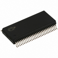
CY7C66113-PVC Cypress Semiconductor Corp, CY7C66113-PVC Datasheet - Page 4

CY7C66113-PVC
Manufacturer Part Number
CY7C66113-PVC
Description
IC MCU 8K USB HUB 4 PORT 56TSSOP
Manufacturer
Cypress Semiconductor Corp
Specifications of CY7C66113-PVC
Applications
USB Hub/Microcontroller
Core Processor
M8
Program Memory Type
OTP (8 kB)
Controller Series
USB Hub
Ram Size
256 x 8
Interface
I²C, USB, HAPI
Number Of I /o
31
Voltage - Supply
4 V ~ 5.5 V
Operating Temperature
0°C ~ 70°C
Mounting Type
Surface Mount
Package / Case
56-SSOP
Operating Temperature (max)
70C
Operating Temperature (min)
0C
Operating Temperature Classification
Commercial
Mounting
Surface Mount
Pin Count
56
Lead Free Status / RoHS Status
Contains lead / RoHS non-compliant
For Use With
CY3649 - PROGRAMMER HI-LO USB M8428-1339 - KIT LOW SPEED PERSONALITY BOARD
Lead Free Status / RoHS Status
Not Compliant, Contains lead / RoHS non-compliant
Other names
428-1330
Available stocks
Company
Part Number
Manufacturer
Quantity
Price
Company:
Part Number:
CY7C66113-PVC
Manufacturer:
CY
Quantity:
10
Figure 10-1. Timer Register 0x24 (read only) .................................................................................. 20
Figure 10-2. Timer Register 0x25 (read only) .................................................................................. 20
Figure 10-3. Timer Block Diagram .................................................................................................... 21
Figure 11-1. HAPI/I
Figure 12-1. I
Figure 12-2. I
Figure 14-1. Processor Status and Control Register 0xFF ............................................................ 23
Figure 15-1. Global Interrupt Enable Register 0x20 (read/write) ................................................... 24
Figure 15-2. USB Endpoint Interrupt Enable Register 0x21 (read/write) ...................................... 24
Figure 17-1. Hub Port Connect Status 0x48 (read only) ................................................................. 28
Figure 17-2. Hub Port Speed 0x4A (read only) ................................................................................ 28
Figure 17-3. Hub Port Enable Register 0x49 (read/write) ............................................................... 28
Figure 17-4. Hub Downstream Ports Control Register 0x4B (read/write) ..................................... 28
Figure 17-5. Hub Ports SE0 Status Register 0x4F (read only) ....................................................... 29
Figure 17-6. Hub Ports Data Register 0x50 (read only) .................................................................. 29
Figure 17-7. Hub Ports Suspend Register 0x4D (read/write) ......................................................... 29
Figure 17-8. Hub Ports Resume Status Register 0x4E (read only) ............................................... 29
Figure 17-9. USB Status and Control Register 0x1F (read/write) .................................................. 29
Figure 18-1. USB Device Address Registers 0x10, 0x40 (read/write) ........................................... 30
Figure 18-2. USB Device Endpoint Zero Mode Registers 0x12 and 0x42, (read/write) ............... 31
Figure 18-3. USB Non-Control Device Endpoint Mode Registers 0x14, 0x16, 0x44, (read/write) 31
Figure 18-4. USB Device Counter Registers 0x11, 0x13, 0x15, 0x41, 0x43 (read/write) .............. 31
Figure 22-1. Clock Timing ................................................................................................................. 37
Figure 22-2. USB Data Signal Timing ............................................................................................... 38
Figure 22-3. HAPI Read by External Interface from USB Microcontroller .................................... 38
Figure 22-4. HAPI Write by External Device to USB Microcontroller ............................................ 39
Table 4-1. Pin Assignments ................................................................................................................ 9
Table 4-2. I/O Register Summary ........................................................................................................ 9
Table 4-3. Instruction Set Summary ................................................................................................. 11
Table 8-1. Port Configurations ......................................................................................................... 18
Table 11-1. HAPI Port Configuration ................................................................................................ 21
Table 11-2. I
Table 15-1. Interrupt Vector Assignments ....................................................................................... 25
Table 17-1. Control Bit Definition for Downstream Ports ..............................................................29
Table 17-2. Control Bit Definition for Upstream Port ..................................................................... 30
Table 18-1. Memory Allocation for Endpoints ................................................................................ 30
Table 19-1. USB Register Mode Encoding ...................................................................................... 32
Table 19-2. Decode table for Table 19-3 : “Details of Modes for Differing Traffic Conditions” ....33
Table 19-3. Details of Modes for Differing Traffic Conditions .......................................................34
Table 22-1. HAPI Read Cycle Timing ...............................................................................................38
Table 22-2. HAPI Write Cycle Timing ...............................................................................................39
2
2
2
C Port Configuration ...................................................................................................22
C Status & Control 0x28 (read/write) ........................................................................ 22
C Data 0x29 (read/write) ............................................................................................ 22
2
C Configuration Register 0x09 (read/write) ................................................... 21
PRELIMINARY
LIST OF FIGURES
LIST OF TABLES
4
(continued)
CY7C66011/12/13
CY7C66111/12/13


