AD9957BSVZ Analog Devices Inc, AD9957BSVZ Datasheet - Page 57
AD9957BSVZ
Manufacturer Part Number
AD9957BSVZ
Description
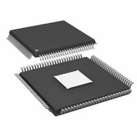
IC DDS 1GSPS 14BIT IQ 100TQFP
Manufacturer
Analog Devices Inc
Datasheet
1.AD9957BSVZ-REEL.pdf
(64 pages)
Specifications of AD9957BSVZ
Resolution (bits)
14 b
Master Fclk
1GHz
Tuning Word Width (bits)
32 b
Voltage - Supply
1.8V, 3.3V
Operating Temperature
-40°C ~ 85°C
Mounting Type
Surface Mount
Package / Case
100-TQFP Exposed Pad, 100-eTQFP, 100-HTQFP, 100-VQFP
Frequency Range
60MHz To 1GHz
Rf Type
Quadrature
Supply Voltage Range
1.71V To 1.89V, 3.135V To 3.465
Rf Ic Case Style
TQFP
No. Of Pins
100
Operating Temperature Range
-40°C To +85°C
Operating Temperature (max)
85C
Operating Temperature (min)
-40C
Pin Count
100
Mounting
Surface Mount
Case Height
1mm
Screening Level
Industrial
Lead Free Status / RoHS Status
Lead free / RoHS Compliant
For Use With
AD9957/PCBZ - BOARD EVAL AD9957 QUADRATURE MOD
Lead Free Status / Rohs Status
Compliant
Available stocks
Company
Part Number
Manufacturer
Quantity
Price
Company:

Part Number:
AD9957BSVZ
Manufacturer:
AD
Quantity:
1 200
Company:
Part Number:
AD9957BSVZ
Manufacturer:
Analog Devices Inc
Quantity:
10 000
Part Number:
AD9957BSVZ
Manufacturer:
ADI/亚德诺
Quantity:
20 000
Company:
Part Number:
AD9957BSVZ-REEL
Manufacturer:
Analog Devices Inc
Quantity:
10 000
Part Number:
AD9957BSVZ-REEL
Manufacturer:
ADI/亚德诺
Quantity:
20 000


Bit (s)
21:17
16
15:14
13
12
11
10
9
8
7
6
5
4:0
Mnemonic
Open
Read Effective
FTW
I/O Update Rate
Control
PDCLK Rate
Control
Data Format
PDCLK Enable
PDCLK Invert
TxEnable Invert
Q-First Data
Pairing
Matched Latency
Enable
Data Assembler
Hold Last Value
Sync Timing
Validation Disable
Open
Description
0: a serial I/O port read operation of the FTW register reports the contents of the FTW register (default).
1: a serial I/O port read operation of the FTW register reports the actual 32-bit word appearing at the input to
the DDS phase accumulator.
Ineffective unless CFR2<23> = 1. Sets the prescale ratio of the divider that clocks the I/O update timer as
follows:
Ineffective unless CFR2<31> = 0 and CFR1<25:24> = 00b.
0: the data-words applied to Pin D<17:0> are expected to be coded as twos complement (default).
1: the data-words applied to Pin D<17:0> are expected to be coded as offset binary.
0: the PDCLK pin is disabled and forced to a static Logic 0 state; the internal clock signal continues to operate
and provide timing to the data assembler.
1: the internal PDCLK signal appears at the PDCLK pin (default).
0: normal PDCLK polarity; Q-data associated with Logic 1, I-data with Logic 0 (default).
1: inverted PDCLK polarity.
0: normal TxENABLE polarity; Logic 0 is standby, Logic 1 is transmit (default).
1: inverted TxENABLE polarity; Logic 0 is transmit, Logic 1 is standby.
0: an I/Q data pair is delivered as I-data first, followed by Q-data (default).
1: an I/Q data pair is delivered as Q-data first, followed by I-data.
0: simultaneous application of amplitude, phase, and frequency changes to the DDS arrive at the output in
the order listed (default).
1: simultaneous application of amplitude, phase, and frequency changes to the DDS arrive at the output
simultaneously.
Ineffective when CFR1<25:24> = 01b.
0: enables the setup and hold validation circuit to take a measurement; the measurement result appears at
the SYNC_SMP_ERR pin; a Logic 1 at this pin indicates a potential setup/hold violation whereas a Logic 0
indicates that a setup/hold violation has not been detected; the measurement result is latched and held until
this bit is set to a Logic 1.
1: resets the setup and hold validation measurement circuit forcing the SYNC_SMP_ERR pin to a static Logic 0
condition (default); the measurement circuit is effectively disabled until this bit is restored to a Logic 0 state.
0: when the TxENABLE pin is false, the data assembler ignores the input data and internally forces zeros on
the baseband signal path (default).
1: when the TxENABLE pin is false, the data assembler ignores the input data and internally forces the last
value received on the baseband signal path.
00: divide-by-1 (default).
01: divide-by-2.
10: divide-by-4.
11: divide-by-8.
0: PDCLK operates at the input data rate (default).
1: PDCLK operates at ½ the input data rate; useful for maintaining a consistent relationship between I/Q
words at the parallel data port and the internal clocks of the baseband signal processing chain.
Rev. B | Page 57 of 64
AD9957
Related parts for AD9957BSVZ
Image
Part Number
Description
Manufacturer
Datasheet
Request
R

Part Number:
Description:
D/A Converter Evaluation Board
Manufacturer:
Analog Devices Inc
Datasheet:


Part Number:
Description:
±1.7g Dual-Axis IMEMS Accelerometer Evaluation Board
Manufacturer:
Analog Devices Inc
Datasheet:

Part Number:
Description:
Inertial Sensor Evaluation System
Manufacturer:
Analog Devices Inc
Datasheet:
Part Number:
Description:
Manufacturer:
Analog Devices Inc
Datasheet:
Part Number:
Description:
Manufacturer:
Analog Devices Inc
Datasheet:
Part Number:
Description:
Manufacturer:
Analog Devices Inc
Datasheet:
Part Number:
Description:
Manufacturer:
Analog Devices Inc
Datasheet:
Part Number:
Description:
Manufacturer:
Analog Devices Inc
Datasheet:
Part Number:
Description:
Manufacturer:
Analog Devices Inc
Datasheet:
Part Number:
Description:
Manufacturer:
Analog Devices Inc
Datasheet:
Part Number:
Description:
Manufacturer:
Analog Devices Inc
Datasheet:
Part Number:
Description:
Manufacturer:
Analog Devices Inc
Datasheet: