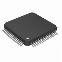
DS26521L+ Maxim Integrated Products, DS26521L+ Datasheet - Page 71

DS26521L+
Manufacturer Part Number
DS26521L+
Description
IC TXRX T1/E1/J1 64-LQFP
Manufacturer
Maxim Integrated Products
Type
Line Interface Units (LIUs)r
Datasheet
1.DS26521LN.pdf
(258 pages)
Specifications of DS26521L+
Number Of Drivers/receivers
1/1
Protocol
T1/E1/J1
Voltage - Supply
3.135 V ~ 3.465 V
Mounting Type
Surface Mount
Package / Case
64-LQFP
Product
Framer
Number Of Transceivers
1
Data Rate
44.736 Mbps
Supply Voltage (max)
3.465 V
Supply Voltage (min)
3.135 V
Supply Current (max)
220 mA
Maximum Operating Temperature
+ 85 C
Minimum Operating Temperature
- 40 C
Mounting Style
SMD/SMT
Lead Free Status / RoHS Status
Lead free / RoHS Compliant
- Current page: 71 of 258
- Download datasheet (2Mb)
8.11.2.1
The DS26521 transmitters can be selected individually to meet the pulse templates for E1 and T1/J1 modes. The
T1/J1 pulse template is shown in
shape can be configured for each LIU on an individual basis. The LIU transmit impedance selection registers can
be used to select an internal transmit terminating impedance of 100Ω for T1, 110Ω for J1 mode, 75Ω or 120Ω for
E1 mode or no internal termination for E1 or T1 mode. The transmit pulse shape and terminating impedance is
selected by
measured for compliance at the appropriate network interface (NI). For T1 long haul and E1, the pulse shape is
measured at the far end. For T1 short haul, the pulse shape is measured at the near end.
Figure 8-18. T1/J1 Transmit Pulse Templates
LTITSR
DSX - 1 Template (pe r ANSI T1.102-1993
Transmit-Line Pulse Shapes
- 0.1
- 0.2
- 0.3
- 0.4
- 0.5
1.2
1.1
1.0
0.9
0.8
0.7
0.6
0.5
0.4
0.3
0.2
0.1
0
- 500
registers. The pulse shapes will be complaint to T1.102 and G.703. Pulse shapes are
MAXIMUM CURVE
- 0.77
- 0.39
- 0.27
- 0.27
- 0.12
0.00
0.27
0.35
0.93
1.16
UI
- 400
Time
- 500
- 255
- 175
- 175
- 75
0
175
225
600
750
T1.102/87, T1.403,
CB 119 (Oct. 79), &
I.431 Template
- 300
Amp.
0.05
0.05
0.80
1.15
1.15
1.05
1.05
- 0.07
0.05
0.05
Figure
- 200
- 0.77
- 0.23
- 0.23
- 0.15
0.00
0.15
0.23
0.23
0.46
0.66
0.93
1.16
MINIMUM CURVE
UI
8-18. The E1 pulse template is shown in
Tim e
- 500
- 150
- 150
- 100
0
100
150
150
300
430
600
750
- 100
Amp.
-0.05
-0.05
0.50
0.95
0.95
0.90
0.50
-0.45
-0.45
-0.20
-0.05
-0.05
0
71 of 258
TIME (ns)
DS1 Template (per ANSI T1.403-1995
100
MAXIMUM CURVE
-0.77
-0.39
-0.27
-0.27
-0.12
0.00
0.27
0.34
0.77
1.16
UI
Time
-500
-255
-175
-175
-75
0
175
225
600
750
200
Amp.
0.05
0.05
0.80
1.20
1.20
1.05
1.05
-0.05
0.05
0.05
300
-0.77
-0.23
-0.23
-0.15
0.00
0.15
0.23
0.23
0.46
0.61
0.93
1.16
MINIMUM CURVE
UI
400
DS26521 Single T1/E1/J1 Transceiver
Time
-500
-150
-150
-100
0
100
150
150
300
430
600
750
500
Figure
Amp.
-0.05
-0.05
0.50
0.95
0.95
0.90
0.50
-0.45
-0.45
-0.26
-0.05
-0.05
600
8-19. The transmit pulse
700
Related parts for DS26521L+
Image
Part Number
Description
Manufacturer
Datasheet
Request
R

Part Number:
Description:
MAX7528KCWPMaxim Integrated Products [CMOS Dual 8-Bit Buffered Multiplying DACs]
Manufacturer:
Maxim Integrated Products
Datasheet:

Part Number:
Description:
Single +5V, fully integrated, 1.25Gbps laser diode driver.
Manufacturer:
Maxim Integrated Products
Datasheet:

Part Number:
Description:
Single +5V, fully integrated, 155Mbps laser diode driver.
Manufacturer:
Maxim Integrated Products
Datasheet:

Part Number:
Description:
VRD11/VRD10, K8 Rev F 2/3/4-Phase PWM Controllers with Integrated Dual MOSFET Drivers
Manufacturer:
Maxim Integrated Products
Datasheet:

Part Number:
Description:
Highly Integrated Level 2 SMBus Battery Chargers
Manufacturer:
Maxim Integrated Products
Datasheet:

Part Number:
Description:
Current Monitor and Accumulator with Integrated Sense Resistor; ; Temperature Range: -40°C to +85°C
Manufacturer:
Maxim Integrated Products

Part Number:
Description:
TSSOP 14/A�/RS-485 Transceivers with Integrated 100O/120O Termination Resis
Manufacturer:
Maxim Integrated Products

Part Number:
Description:
TSSOP 14/A�/RS-485 Transceivers with Integrated 100O/120O Termination Resis
Manufacturer:
Maxim Integrated Products

Part Number:
Description:
QFN 16/A�/AC-DC and DC-DC Peak-Current-Mode Converters with Integrated Step
Manufacturer:
Maxim Integrated Products

Part Number:
Description:
TDFN/A/65V, 1A, 600KHZ, SYNCHRONOUS STEP-DOWN REGULATOR WITH INTEGRATED SWI
Manufacturer:
Maxim Integrated Products

Part Number:
Description:
Integrated Temperature Controller f
Manufacturer:
Maxim Integrated Products

Part Number:
Description:
SOT23-6/I�/45MHz to 650MHz, Integrated IF VCOs with Differential Output
Manufacturer:
Maxim Integrated Products

Part Number:
Description:
SOT23-6/I�/45MHz to 650MHz, Integrated IF VCOs with Differential Output
Manufacturer:
Maxim Integrated Products

Part Number:
Description:
EVALUATION KIT/2.4GHZ TO 2.5GHZ 802.11G/B RF TRANSCEIVER WITH INTEGRATED PA
Manufacturer:
Maxim Integrated Products

Part Number:
Description:
QFN/E/DUAL PCIE/SATA HIGH SPEED SWITCH WITH INTEGRATED BIAS RESISTOR
Manufacturer:
Maxim Integrated Products
Datasheet:


