FLUKE-284 Fluke, FLUKE-284 Datasheet - Page 6
FLUKE-284
Manufacturer Part Number
FLUKE-284
Description
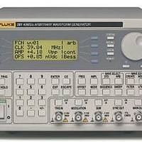
Function Generators & Synthesizers 4 CHANNEL ARBITRARY 40 MS/S WAVEFORM GEN
Manufacturer
Fluke
Datasheet
1.FLUKE-284.pdf
(8 pages)
Specifications of FLUKE-284
Frequency
1 mHz to 10 MHz
Equipment Type
Waveform Generator
Lead Free Status / Rohs Status
Lead free / RoHS Compliant
Other names
2423199


Operating modes
Continuous
Waveform runs continuously.
Triggered burst
Each active edge of the trigger signal will produce one burst
of the waveform.
Gated
Waveform will run while the Gate signal is true and stop while false.
Sweep
Frequency sweep capability is provided for both standard and
arbitrary wave forms. Arbitrary waveforms are expanded or con-
densed to exactly 4096 points and DDS techniques are used to
perform the sweep.
Carrier waveforms
Max. carrier
frequency
Number of cycles
Trigger repetition
Trigger signal Source
Trigger start/stop
phase
Carrier waveforms
Max. carrier
frequency
Number of cycles
Trigger repetition
Gate signal source
Gate start/stop phase
Carrier waveforms
Sweep mode
Sweep direction
Sweep range
Sweep time
Marker
Sweep trigger source
Sweep hold
280 Series
All standard and arbitrary except pulse, pulse train
and sequence
Linear or logarithmic, triggered or continuous
Up, down, up/down or down/up.
From 1 mHz to 16 MHz in
one range
30 ms to 999 s
Variable during sweep
The sweep may be free run or triggered from the
following: Manually from keyboard. Externally from
TRIG IN input or remote interface
Sweep can be held / restarted by the HOLD key
280 Series
All standard and arbitrary waveforms
1 MHz or the maximum
for the selected wave form
if lower. 40 Msamples/s
for ARB and Sequence
1 to 1,048,575
0.005 Hz to 100 kHz internal, dc to 1 MHz external
Internal from keyboard, previous channel, next
channel or trigger generator. External from TRIG IN
or remote interface.
± 360° settable with 0.1° resolution, subject to
waveform frequency and type
280 Series
All standard and arbitrary waveforms
1 MHz or the maxi-
mum for the selected
wave form if lower. 40
Msamples/s for ARB and
Sequence.
1 to 1,048,575
0.005 Hz to 100 kHz internal, dc to 1 MHz external.
Internal from keyboard, previous channel, next
channel or trigger generator. External from TRIG IN
or remote interface.
± 360° settable with 0.1° resolution, subject to
waveform frequency and type.
290 Series
2.5 MHz or the maxi-
mum for the selected
waveform if lower. 100
Msamples/s for ARB and
Sequence.
290 Series
From 1 mHz to 40 MHz in
one range
1 ms to 999 s
290 Series
2.5 MHz or the maxi-
mum for the selected
waveform if lower. 100
Msamples/s for ARB and
Sequence
Multi channel sweep
(multi-channel units only)
Any number of channels may be swept simul-
taneously. Amplitude, Offset and Waveform can
be set independently for each channel. For Fluke
280 units the sweep parameters will be the
same for all channels. For Fluke 290 units the
sweep parameters can be set independently for
each channel.
Tone switching
Capability provided for both standard and
arbitrary waveforms. Arbitrary wave forms are
expanded or condensed to exactly 4096 points
and DDS techniques are used to allow instanta-
neous frequency switching.
Carrier
waveforms
Frequency
list
Trigger
repetition
rate
Trigger
source
Tone
switching
modes
Tone switching modes:
Gated: The tone is output while the trigger
signal is true and stopped, at the end of the
current waveform cycle, while the trigger
signal is false. The next tone is output
when the trigger signal is true again.
Triggered: The tone is output when the
trigger signal goes true and the next tone is
output, at the end of the current waveform
cycle, when the trigger signal goes true
again.
FSK: The tone is output when the trigger
signal goes true and the next tone is
output, immediately, when the trigger
signal goes true again. Using 2 channels
with their outputs summed together it is
possible to generate DTMF test signals.
Trigger generator: Internal source 0.005
Hz to 100 kHz square wave adjustable in
10 us steps. 3-digit resolution. Available for
external use from any SYNC OUT socket.
280 Series
All except pulse, pulse train and sequence
Up to 16
frequencies from
1 mHz to 10 MHz
0.005 Hz to 100 kHz internal. dc to 1MHz
exter nal. Usable repetition rate and
waveform fre quency depend on the tone
switching mode.
Internal from keyboard, previous channel,
next channel or trigger generator. External
from TRIG IN or remote interface.
Gated, Triggered or FSK (see box top right)
290 Series
Up to 16 frequencies
from 1mHz to 40 MHz
Outputs
Main output—One for each channel
Auxiliary sine output
Sync out—One for each channel
Multifunction output user definable or automatically selected to
be any of the following:
Output impedance
Amplitude range
Amplitude accuracy
Amplitude flatness
DC offset range
DC offset accuracy
Resolution
280 Series
n/a
Waveform sync: (all waveforms)
Position markers: (Arbitrary only)
Burst done
Sequence sync
Trigger
Sweep sync
Sweep marker
Phase lock out
Signal level
Signal level: (sweep sync. only)
290 Series
n/a
280 Series
50 Ω
5 mV to 20 V pp open circuit (2.5 mV to 10 V pp into
50 Ω). Amplitude can be specified open cir cuit (hi Z)
or into an assumed load of 50 Ω or 600 Ω in Vpk-pk,
Vrms or dBm.
2 % ± 1 mV at 1 kHz into 50 Ω
± 0.2 dB to 200 kHz;
± 1dB to 10 MHz;
± 2.5 dB to 16 MHz
± 10 V from 50 Ω. Offset plus signal peak limited
to ± 10 V.
Typically 3 % ± 10 mV, unattenuated
3 digits or 1 mV for both Amplitude and DC Offset
292/294
Nominal 1V p-p sinewave, frequency set by
system clock, frequency 0.1 Hz to 50 MHz
Logic levels of < 0.8 V and > 3 V for
all outputs
280 Series
Square wave with 50 % duty cycle at the main waveform frequency, or pulse
coincident with the first few points of an arbitrary waveform
Any point(s) on the waveform may have associated marker bit(s) set high or low
Produces a pulse coincident with the last cycle of a burst
Produces a pulse coincident with the end of a waveform sequence
Selects the current trigger signal. Useful for syn chronizing burst or gated signals.
Outputs a pulse at the start of sweep to synchronize an oscilloscope or recorder
N/A
Used to phase lock two generators. Produces a positive edge at the 0° phase point.
N/A
290 Series
± 0.2 dB to 1 MHz;
± 0.4 dB to 40 MHz
Logic levels of < 0.8 V and > 3 V for
all outputs except Sweep Sync
290 Series
Additional pulse for use as sweep marker
3 level waveform - as above but plus
narrow +1 V pulse at marker
Single and Multi-Channel Universal ARB Generators
11