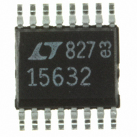
LTC1563-2CGN#PBF Linear Technology, LTC1563-2CGN#PBF Datasheet - Page 12

LTC1563-2CGN#PBF
Manufacturer Part Number
LTC1563-2CGN#PBF
Description
IC FILTER LP RC 4TH ORDER 16SSOP
Manufacturer
Linear Technology
Datasheet
1.LTC1563-2CGNPBF.pdf
(20 pages)
Specifications of LTC1563-2CGN#PBF
Filter Type
Butterworth, Lowpass Switched Capacitor
Frequency - Cutoff Or Center
256kHz
Number Of Filters
1
Max-order
4th
Voltage - Supply
2.7 V ~ 11 V, ±2.7 V ~ 5.5 V
Mounting Type
Surface Mount
Package / Case
16-SSOP
Lead Free Status / RoHS Status
Lead free / RoHS Compliant
Available stocks
Company
Part Number
Manufacturer
Quantity
Price
LTC1563-2/LTC1563-3
APPLICATIONS
should be much larger than RA1 to minimize the interac-
tion of this pole with the 2nd order section. This circuit is
useful in forming dual 3rd order filters and 5th order filters
with a single LTC1563 part. By cascading two parts, 7th
order and 9th order filters are achieved.
You can also use the TEE network in both sections of the
part to make a 6th order filter. This 6th order filter does not
conform exactly to the textbook responses. Textbook
responses (Butterworth, Bessel, Chebyshev etc.) all have
three complex pole pairs. This filter has two complex pole
pairs and two real poles. The textbook response always
has one section with a low Q value between 0.5 and 0.6. By
replacing this low Q section with two real poles (two real
poles are the same mathematically as a complex pole pair
with a Q of 0.5) and tweaking the Q of the other two
complex pole pair sections you end up with a filter that is
indistinguishable from the textbook filter. The Typical
Applications section illustrates a 100kHz, 6th order pseudo-
Butterworth filter. FilterCAD is a valuable tool for custom
filter design and tweaking textbook responses.
12
DC GAIN =
F
1/2 LTC1563
P
(OPEN)
=
V
2π • R2 • C1
IN
S
C2
1
–R2
R1
R1
AGND
U
INV
LTC1563-2: C1A = 53.9pF, C1B = 39.2pF
LTC1563-3: C1A = 35pF, C1B = 26.8pF
Figure 2
INFORMATION
U
–
+
C1
R2
W
LP
V
OUT
1563 F02
U
What To Do with an Unused Section
If the LTC1563 is used as a 2nd or 3rd order filter, one of
the sections is not used. Do not leave this section uncon-
nected. If the section is left unconnected, the output is left
to float and oscillation may occur. The unused section
should be connected as shown in Figure 4 with the INV pin
connected to the LP pin and the S pin left open.
RA1
1/2 LTC1563
(OPEN)
C
RB1
P
S
RA1 ≈
F
C2
1/2 LTC1563
P
=
2π •
AGND
S
RB1
10
C2
(
RA1 + RB1
RA1 • RB1
INV
R2
1
AGND
Figure 3
Figure 4
–
+
)
INV
C
P
C1
–
+
R3
C1
LP
1563 F04
LP
156323fa
1563 F03


