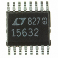
LTC1563-2CGN#PBF Linear Technology, LTC1563-2CGN#PBF Datasheet - Page 16

LTC1563-2CGN#PBF
Manufacturer Part Number
LTC1563-2CGN#PBF
Description
IC FILTER LP RC 4TH ORDER 16SSOP
Manufacturer
Linear Technology
Datasheet
1.LTC1563-2CGNPBF.pdf
(20 pages)
Specifications of LTC1563-2CGN#PBF
Filter Type
Butterworth, Lowpass Switched Capacitor
Frequency - Cutoff Or Center
256kHz
Number Of Filters
1
Max-order
4th
Voltage - Supply
2.7 V ~ 11 V, ±2.7 V ~ 5.5 V
Mounting Type
Surface Mount
Package / Case
16-SSOP
Lead Free Status / RoHS Status
Lead free / RoHS Compliant
Available stocks
Company
Part Number
Manufacturer
Quantity
Price
LTC1563-2/LTC1563-3
TEXTBOOK BUTTERWORTH
f
f
f
Other Pseudo Filter Response Coefficients (All f
f
Q1
f
Q2
f
f
The f
FilterCAD’s Enhanced Design window as a custom re-
sponse filter. After entering the coefficients, FilterCAD will
produce a schematic of the circuit. The procedure is as
follows:
1. After starting FilterCAD, select the Enhanced Design
2. Select the Custom Response and set the custom F
3. In the Coefficients table, go to the Type column and click
16
TYPICAL APPLICATIO S
O
O
O
O
O
O
O
1 = 100kHz
2 = 100kHz
3 = 100kHz
1
2
3
4
V
IN
window.
1Hz.
on the types listed and set the column with two LP types
and two LP1 types. This sets up a template of a 6th order
filter with two 2nd order lowpass sections and two 1st
order lowpass sections.
R
A1
BESSEL
1.9070
1.0230
1.6910
0.6110
1.6060
1.6060
O
3.16k
and Q values listed above can be entered in
R
100kHz, 6th Order Pseudo-Butterworth
B1
C11
560pF
Q1 = 1.9319
Q2 = 0.7071
Q3 = 0.5176
0.1dB RIPPLE CHEBYSHEV
29.4k
0.1µF
32.4k
17.8k
R21
R31
1.0600
3.8500
0.8000
1.0000
0.6000
1.0000
1
2
3
4
5
6
7
8
LP
SA
NC
INVA
NC
LPA
AGND
V
R
PSEUDO-BUTTERWORTH
f
f
f
f
–
A2
O
O
O
O
LTC1563-2
1 = 100kHz Q1 = 1.9319
2 = 100kHz Q2 = 0.7358
3 = 100kHz Real Poles
4 = 100kHz Real Poles
3.16k
U
INVB
LPB
NC
NC
SB
NC
EN
V
0.5dB RIPPLE CHEBYSHEV
+
R
B2
16
15
14
13
12
11
10
9
C12
560pF
25.5k
O
28.7k
20.5k
R22
R32
Are Normalized for a 1Hz Filter Cutoff)
1.0100
5.3000
0.7200
1.2000
0.5000
0.8000
0.1µF
1563 TA07
V
3.3V
C
OUT
to
TRANSITIONAL GAUSSIAN TO 12dB
The complex, 2nd order section of the textbook design
with the lowest Q is replaced with two real first order poles.
The Q of another section is slightly altered such that the
final filter’s response is indistinguisable from a textbook
Butterworth response.
4. Enter the f
5. Set the custom F
6. Click on the Implement button to go on to the filter
7. In the Enhanced Implement window, click on the Active
Butterworth filter, use the same coefficients as the
example circuit above except set all of the f
will automatically multiply all of the f
have now finished the design of the filter and you can
click on the frequency response or step response
buttons to verify the filter’s response.
implementation stage.
RC button to choose the LTC1563-2 part. You are now
done with the filter’s implementation. Click on the
schematic button to view the resulting circuit.
2.1000
2.2000
1.2500
0.8000
1.2500
1.2500
O
–100
–10
–20
–30
–40
–50
–60
–70
–80
–90
10
and Q coefficients as listed above. For a
0
10k
C
Frequency Response
to the desired cutoff frequency. This
FREQUENCY (Hz)
100k
TRANSITIONAL GAUSSIAN TO 6dB
O
1563 TA07a
coefficients. You
1.5000
2.8500
1.0500
0.9000
0.9000
0.9000
1M
O
to 1Hz.
156323fa


