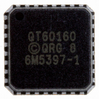
QT60160-ISG Atmel, QT60160-ISG Datasheet - Page 5

QT60160-ISG
Manufacturer Part Number
QT60160-ISG
Description
SENSOR IC MTRX TOUCH16KEY 32-QFN
Manufacturer
Atmel
Series
QMatrix™r
Type
Capacitiver
Datasheet
1.QT60160-ISG.pdf
(26 pages)
Specifications of QT60160-ISG
Number Of Inputs/keys
16 Key
Resolution (bits)
10 b
Data Interface
I²C, Serial, SPI™
Voltage Reference
External
Voltage - Supply
1.8V, 3.3V, 5V
Current - Supply
4.6mA
Operating Temperature
-40°C ~ 85°C
Mounting Type
Surface Mount
Package / Case
32-MLF®, QFN
Output Type
*
Interface
*
Input Type
*
Operating Supply Voltage
1.8 V to 5.5 V
Maximum Operating Temperature
+ 85 C
Mounting Style
SMD/SMT
Minimum Operating Temperature
- 40 C
Lead Free Status / RoHS Status
Lead free / RoHS Compliant
Other names
427-1125-2
Available stocks
Company
Part Number
Manufacturer
Quantity
Price
Company:
Part Number:
QT60160-ISG
Manufacturer:
NSC
Quantity:
622
Company:
Part Number:
QT60160-ISG QS129
Manufacturer:
LTC
Quantity:
1 190
QmBtn software is available free of charge on Quantum’s
website www.qprox.com.
The signal swing from the smallest finger touch should
preferably exceed 8 counts, with 12 being a reasonable
target. The signal threshold setting (NTHR) should be set to a
value guaranteed to be less than the signal swing caused by
the smallest touch.
Increasing the burst length (BL) parameter will increase the
signal strengths as will increasing the sampling resistor (Rs)
values.
2.7 Matrix Series Resistors
The X and Y matrix scan lines can use series resistors
(referred to as Rx and Ry respectively) for improved EMC
performance (Figure 2.7, page 9).
X drive lines require Rx in most cases to reduce edge rates
and thus reduce RF emissions. Typical values range from
1K
Y lines need Ry to reduce EMC susceptibility problems and in
some extreme cases, ESD. Typical Y values are about 1K
Y resistors act to reduce noise susceptibility problems by
forming a natural low-pass filter with the Cs capacitors.
It is essential that the Rx and Ry resistors and Cs capacitors
be placed very close to the chip. Placing these parts more
than a few millimeters away opens the circuit up to high
frequency interference problems (above 20MHz) as the trace
lengths between the components and the chip start to act as
RF antennae.
lQ
✡
to 20K
✡
.
Figure 2.5 Probing X-Drive
Waveforms With a Coin
✡
.
5
The upper limits of Rx and Ry are reached when the signal
level and hence key sensitivity are clearly reduced. The limits
of Rx and Ry will depend on key geometry and stray
capacitance, and thus an oscilloscope is required to
determine optimum values of both.
Dwell time is the duration in which charge coupled from X to
Y is captured (Figure 2.4, page 4). Increasing Rx values will
cause the leading edge of the X pulses to increasingly roll off,
causing the loss of captured charge (and hence loss of signal
strength) from the keys.
The dwell time of these parts is fixed at 500ns. If the X pulses
have not settled within 500ns, key gain will be reduced; if this
happens, either the stray capacitance on the X line(s) should
be reduced (by a layout change, for example by reducing X
line exposure to nearby ground planes or traces), or, the Rx
resistor needs to be reduced in value (or a combination of
both approaches).
‘T’ should ideally be similar to the complete thickness the fields
need to penetrate to the touch surface. Smaller dimensions will also
work but will give less signal strength. If in doubt, make the pattern
coarser. The lower figure shows a simpler structure used for
compact key layouts, for example for mobile phones. A layout with a
common X drive and three receive electrodes is depicted.
Figure 2.6 Recommended Key Structure
X0
QT60240-ISG R8.06/0906
Y0
Y1
Y2


