AD693AD Analog Devices Inc, AD693AD Datasheet - Page 9
AD693AD
Manufacturer Part Number
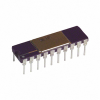
AD693AD
Description
IC SGNL COND 4-20MA TX 20-CDIP
Manufacturer
Analog Devices Inc
Type
Signal Conditionerr
Datasheet
1.AD693AQ.pdf
(12 pages)
Specifications of AD693AD
Rohs Status
RoHS non-compliant
Input Type
Voltage
Output Type
Voltage
Interface
3-Wire
Current - Supply
20mA
Mounting Type
Through Hole
Package / Case
20-CDIP (0.300", 7.62mm)
No. Of Amplifiers
5
Input Offset Voltage
200µV
Cmrr
90dB
Supply Voltage Range
12V To 36V
Supply Current
500µA
Amplifier Case Style
DIP
No. Of Pins
20
Operating Temperature Range
-40°C To +85°C
Rohs Compliant
No
Available stocks
Company
Part Number
Manufacturer
Quantity
Price

Part Number:
AD693AD
Manufacturer:
ADI/亚德诺
Quantity:
20 000


REV. A
OPTIONAL INPUT FILTERING
Input filtering is recommended for all applications of the
AD693 due to its low input signal range. An RC filter network
at each input of the signal amplifier is sufficient, as shown in
Figure 16. In the case of a resistive signal source it may be
necessary only to add the capacitors, as shown in Figure 18.
The capacitors should be placed as close to the AD693 as
possible. The value of the filter resistors should be kept low to
minimize errors due to input bias current. Choose the 3 dB
point of the filter high enough so as not to compromise the
bandwidth of the desired signal. The RC time constant of the
filter should be matched to preserve the ac common-mode
rejection.
Figure 17. 0-to-104 C Direct Three-Wire 100
Figure 16. Optional Input Filtering
Figure 15. Local Powered Operation with 0–20 mA Output
RTD lnterface, 4-20mA Output
–9–
INTERFACING PLATINUM RTDS
The AD693 has been specially configured to accept inputs from
100
Referring to Figure 17, the RTD and the temperature stable
100
Amplifier resulting in a noninverting gain of (1 + R
where R
The noninverting input of the Auxiliary Amplifier (Pin 2) is
then driven by the 75 mV signal from the Voltage Divider (Pin
4). When the RTD is at 0, its 100
amplifier gain of +2 causing V
Amplifier compares this voltage to the 150 mV output (Pin 3) so
that zero differential signal results. As the temperature (and
therefore, the resistance) of the RTD increases, V
increase according to the gain relationship. The difference
between this voltage and the zero degree value of 150 mV drives
the Signal Amp to modulate the loop current. The AD693 is
precalibrated such that the full 4-20mA output span corresponds
to a 0 to 104 C range in the RTD. (This assumes the European
Standard of
three-wire (or two-wire) RTDs are available using only the pin
strapping options as shown in Table I.
A variety of other temperature ranges can be realized by using
different application voltages. For example, loading the Voltage
Divider with a 1.5 k resistor from Pin 3 to Pin 6 (common)
will approximately halve the original application voltages and
allow for a doubling of the range of resistance (and therefore,
temperature) required to fill the two standard spans. Likewise,
Platinum RTDs (Resistance Temperature Detectors).
resistor form a feedback network around the Auxiliary
T
is the temperature dependent resistance of the RTD.
= 0.00385.) A total of 6 precalibrated ranges for
X
to be 150 mV. The Signal
Temperature
Range
0 to + 104 C
0 to +211 C
+25 C to +130 C
+51 C to +266 C
–50 C to +51 C
–100 C to +104 C 12 to 11 and
Table I. Precalibrated Temperature
Range Options Using a European
Standard 100
resistance results in an
RTD and the AD693
X
AD693
Pin Connections
12 to 13
12 to 13, and
15 to 16
12 to 14
12 to 14, and
15 to 16
12 to 11
15 to 16
T
will likewise
/100 ),
Related parts for AD693AD
Image
Part Number
Description
Manufacturer
Datasheet
Request
R

Part Number:
Description:
±1.7g Dual-Axis IMEMS Accelerometer Evaluation Board
Manufacturer:
Analog Devices Inc
Datasheet:

Part Number:
Description:
Inertial Sensor Evaluation System
Manufacturer:
Analog Devices Inc
Datasheet:
Part Number:
Description:
Manufacturer:
Analog Devices Inc
Datasheet:
Part Number:
Description:
Manufacturer:
Analog Devices Inc
Datasheet:
Part Number:
Description:
Manufacturer:
Analog Devices Inc
Datasheet:
Part Number:
Description:
Manufacturer:
Analog Devices Inc
Datasheet:
Part Number:
Description:
Manufacturer:
Analog Devices Inc
Datasheet:
Part Number:
Description:
Manufacturer:
Analog Devices Inc
Datasheet:
Part Number:
Description:
Manufacturer:
Analog Devices Inc
Datasheet:
Part Number:
Description:
Manufacturer:
Analog Devices Inc
Datasheet:
Part Number:
Description:
Manufacturer:
Analog Devices Inc
Datasheet:
Part Number:
Description:
Manufacturer:
Analog Devices Inc
Datasheet:
Part Number:
Description:
Manufacturer:
Analog Devices Inc
Datasheet: