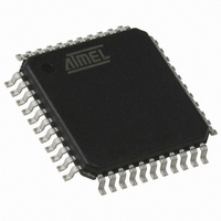
QT60486-ASG Atmel, QT60486-ASG Datasheet - Page 17

QT60486-ASG
Manufacturer Part Number
QT60486-ASG
Description
IC SENSOR QMATRIX 48CHAN 44TQFP
Manufacturer
Atmel
Series
QMatrix™, QProx™r
Type
Capacitiver
Datasheet
1.QT60326-ASG.pdf
(32 pages)
Specifications of QT60486-ASG
Number Of Inputs/keys
48 Key
Resolution (bits)
9, 11 b
Data Interface
Serial, SPI™, UART
Voltage - Supply
4.75 V ~ 5.25 V
Current - Supply
25mA
Operating Temperature
-40°C ~ 105°C
Mounting Type
Surface Mount
Package / Case
44-TQFP, 44-VQFP
Output Type
Logic
Interface
UART, SPI
Input Type
Logic
Operating Supply Voltage
5 V
Maximum Operating Temperature
+ 105 C
Minimum Operating Temperature
- 40 C
Mounting Style
SMD/SMT
For Use With
427-1088 - BOARD EVAL QT60486-AS QMATRIX
Lead Free Status / RoHS Status
Lead free / RoHS Compliant
Other names
427-1110
Available stocks
Company
Part Number
Manufacturer
Quantity
Price
Company:
Part Number:
QT60486-ASG
Manufacturer:
LT
Quantity:
2 488
where changes are specifically required, such as for sensiti vity,
timing, or AKS changes.
The circles in this drawing are communications interchanges
between host and sensor. The rectangles are internal host
states or processing events. If any communications exchange
fails, either the device will fail to respond within the allotted time,
or the response CRC will be incorrect, or the response will be
out of context (the response is clearly not for the intended
command). In these cases the host should just repeat the
command.
The control flow will spend 99% of its time alternating between
the two states within the dashed rectangle. If a key is detected,
the control flow will enter ‘Key Detection Processing’.
Stuck Key Detection processing (0xck) is optional, since the
device contains the max on-duration timeout function and can
therefore recalibrate the stuck key automatically. However, the
host can recalibrate stuck keys with greater flexibility if the
recalibration timeouts are set to infinite and the host recalibrates
them under specific conditions.
lQ
Note: CRC errors or incorrect
responses should cause
each transmission to retry
Power On or Hardware Reset
Figure 4-1 Suggested Communications Flow
m
17
Error handling takes place whenever an error flag is detected,
or the device stops communicating (not shown). The error
handling procedure is up to the designer, however normally this
would entail shutting down the product if the error is serious
enough (for example, a key that will not calibrate, or a FMEA
class error).
Normally it is not required to reload the setups, since the device
itself stores a backup copy of these in Flash memory should the
eeprom become corrupt. However the host should reset the QT
so that the device will copy the Flash setups to eeprom, and
then the QT should check that the eeprom CRC code is correct.
Only if this fails should the eeprom be reloaded by the host.
One exception to this rule is just after powerup, since a CRC
error in the eeprom setups at this point is clearly a critical error
that would require reloading. This happens at the factory, during
the very first powerup cycle.
The ‘Last Command’ command can be used at any time to clear
comms error flags and to resynchronize failed communications,
for example due to timing errors etc.
QT60486-AS R8.01/0105


