CLC020BCQ/NOPB National Semiconductor, CLC020BCQ/NOPB Datasheet - Page 14
CLC020BCQ/NOPB
Manufacturer Part Number
CLC020BCQ/NOPB
Description
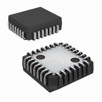
IC SERIALIZER VIDEO DGTL 28-PLCC
Manufacturer
National Semiconductor
Datasheet
1.CLC020BCQNOPB.pdf
(15 pages)
Specifications of CLC020BCQ/NOPB
Function
Serializer
Data Rate
400Mbps
Input Type
CMOS
Output Type
CMOS, TTL
Number Of Inputs
10
Number Of Outputs
1
Voltage - Supply
4.5 V ~ 5.5 V
Operating Temperature
0°C ~ 70°C
Mounting Type
Surface Mount
Package / Case
28-PLCC
For Use With
SD020EVK - BOARD EVALUATION CLC020
Lead Free Status / RoHS Status
Lead free / RoHS Compliant
Other names
*CLC020BCQ
*CLC020BCQ/NOPB
CLC020BCQ
*CLC020BCQ/NOPB
CLC020BCQ
Available stocks
Company
Part Number
Manufacturer
Quantity
Price
Company:

Part Number:
CLC020BCQ/NOPB
Manufacturer:
National Semiconductor
Quantity:
135
Company:
Part Number:
CLC020BCQ/NOPB
Manufacturer:
LT
Quantity:
4 067
Company:
Part Number:
CLC020BCQ/NOPB
Manufacturer:
Texas Instruments
Quantity:
10 000


www.national.com
Application Information
values. New layouts using the CLC020 will benefit from the
greatly reduced ancilliary component count and more com-
pact layout.
The CLC020 does not require external VCO filtering compo-
nents. The external VCO filtering components at pin 17 of
the GS9022 may remain connected to the CLC020 without
complications. It is suggested that these be removed from
the circuit board. The CLC020 uses pin 17 for its test pattern
generator enable function. You will find the TPG function
very useful when you make this change.
Remove the C
The CLC020 uses pin 26 as the BIST pass/fail indicator
output. You may attach a LED as an indicator to this pin, if
desired. LED current should be limited to 10 mA maximum.
The same LED type and current limiting resistor shown in
Figure 8 at the Lock Detect output may be used for this
indicator function.
Remove any capacitor attached to pin 19. A capacitor at-
tached to pin 19 will cause distortion of the output V
The former data rate setting resistor, R
functions as the output level setting resistor, R
changed to a 1.69 kΩ, 1% value for correct output level
setting.
The input series resistors and the P
tor used with the GS9022 are not needed for the CLC020.
These components should be removed from the circuit
board and the resistors replaced by short circuits (0Ω resis-
tors). These series resistors will increase input signal rise
and fall times if left on the board.
OSC
capacitor used by the GS9022 at pin 26.
CLK
risetime filter capaci-
VCO
(Continued)
, at pin 19 now
REF
. It must be
OH
level.
14
The CLC020 has current-mode serial cable driver outputs.
These outputs have very high internal generator resistance
as one would expect of a current source. Though these
current-mode outputs can produce the equivalent drive volt-
ages into the load, it is necessary to change and simplify the
typical GS9022 output circuit normally recommended for that
device. The output load resistors at pins 22 and 23 must be
changed to 75Ω, 1% values. These resistors become the
back-matching loads across which the CLC020’s outputs
develop drive voltage. The series back-matching resistors
used on the GS9022 should be removed and replaced with
short circuits. The risetime compensating capacitors across
these resistors should be removed.
Pin 28 on the CLC020 is V
negative supply or ground. On layouts designed to mount
the GS9022, the series R-C network connected to this pin
should be replaced by short circuits (0Ω resistors).
The pull-up resistor connected to the Lock Detect output, pin
14, should be removed. It may be replaced by a LED and
current limiting resistor connected to V
indicator is desired.
The CLC020 has an internal pull-down at the Sync Detect
Enable input and may be left unconnected in SMPTE video-
only applications.
The CLC020 has independent power supply pins for the
VCO, V
output driver negative supply, V
driver positive supply, V
On new layouts, additional power supply filtering may be
added at these pins, if desired.
SSO
, pin 15 and V
DDSD
DDO
SS
, is pin 24 (as on the GS9022).
and must be connected to the
, pin 16. The CLC020 has an
SSSD
, at pin 21. The output
SS
if a visual lock
Related parts for CLC020BCQ/NOPB
Image
Part Number
Description
Manufacturer
Datasheet
Request
R

Part Number:
Description:
Buffer / Driver / Receiver Logic IC
Manufacturer:
National Semiconductor

Part Number:
Description:
BOARD EVALUATION CLC020
Manufacturer:
National Semiconductor
Datasheet:
Part Number:
Description:
National Semiconductor [8-Bit D/A Converter]
Manufacturer:
National Semiconductor
Datasheet:
Part Number:
Description:
National Semiconductor [Media Coprocessor]
Manufacturer:
National Semiconductor
Datasheet:
Part Number:
Description:
Digitally Controlled Tone and Volume Circuit with Stereo Audio Power Amplifier, Microphone Preamp Stage and National 3D Sound
Manufacturer:
National Semiconductor
Datasheet:
Part Number:
Description:
Digitally Controlled Tone and Volume Circuit with Stereo Audio Power Amplifier, Microphone Preamp Stage and National 3D Sound
Manufacturer:
National Semiconductor
Datasheet:
Part Number:
Description:
AC97 Rev 2 Codec with Sample Rate Conversion and National 3D Sound
Manufacturer:
National Semiconductor
Part Number:
Description:
Manufacturer:
National Semiconductor
Datasheet:
Part Number:
Description:
Manufacturer:
National Semiconductor
Datasheet:
Part Number:
Description:
General Purpose, Low Voltage, Low Power, Rail-to-Rail Output Operational Amplifiers
Manufacturer:
National Semiconductor
Datasheet:
Part Number:
Description:
8-bit 20 MSPS flash A/D converter.
Manufacturer:
National Semiconductor
Datasheet:
Part Number:
Description:
Low Noise Quad Operational Amplifier
Manufacturer:
National Semiconductor
Datasheet:
Part Number:
Description:
Quad Differential Line Receivers
Manufacturer:
National Semiconductor
Datasheet:
Part Number:
Description:
Quad High Speed Trapezoidal? Bus Transceiver
Manufacturer:
National Semiconductor
Datasheet: