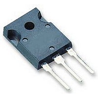
SJDP120R045 SEMISOUTH, SJDP120R045 Datasheet

SJDP120R045
Specifications of SJDP120R045
Related parts for SJDP120R045
SJDP120R045 Summary of contents
Page 1
... Operating and Storage Temperature Lead Temperature for Soldering (1) Pulse width limited by maximum junction temperature ( ohm, t < 200ns, see Figure 5 for static conditions (EXT) p THERMAL CHARACTERISTICS Parameter Thermal Resistance, junction-to-case Thermal Resistance, junction-to-ambient SJDP120R045 Rev1.3 PRELIMINARY 4 TO-247 Symbol Conditions ° TC= 100 ° C ...
Page 2
... Turn-off Delay Fall Time Turn-on Energy Turn-off Energy Total Switching Energy Turn-on Delay Rise Time Turn-off Delay Fall Time Turn-on Energy Turn-off Energy Total Switching Energy Total Gate Charge Gate-Source Charge Gate-Drain Charge SJDP120R045 Rev1.3 PRELIMINARY Symbol Conditions - 1200 µ 1200 - ...
Page 3
... Figure 5. Gate Current I = f(V ); parameter 1.E-02 1.E-03 1.E-04 1.E-05 1.E-06 1.E-07 1.E-08 1.E-09 1.E-10 0.0 0.5 1 Gate-Source Voltage (V) GS SJDP120R045 Rev1.3 PRELIMINARY Figure 2. Typical Output Characteristics GS 2.0 V 1.0 V 0.0 V -1 Figure 4. Typical Transfer Characteristics GS 120 2.0 V 100 1.0 V 0.0 V -1.0 V -2.0 V ...
Page 4
... T , Junction Temperature (°C) j Figure 9. Typical Capacitance 100 kHz DS GS 1.E+04 1.E+03 1.E+02 C rss 1.E+01 0 300 600 V , Drain-Source Voltage (V) DS SJDP120R045 Rev1.3 PRELIMINARY Figure 8. Drain-Source On-resistance 125 150 175 1E-04 1E-05 C iss 1E-06 C oss 1E-07 900 1200 4/6 Silicon Carbide ...
Page 5
... SJDP120R045 Rev1.3 PRELIMINARY SJDP120R045 MILLIMETERS DIM MIN MAX A 4.903 5.157 A1 2.273 2.527 A2 1.853 2.108 b 1.073 1.327 b1 2.873 3.381 b2 1.903 2.386 c 0.600 0.752 D 20.823 21.077 D1 17.393 17.647 D2 1.063 1.317 e 5.450 E 15.773 16.027 E1 13.893 14.147 L 20.053 20.307 L1 4.168 4.472 Q 6.043 6.297 ØP 3.560 3.660 Ø ...
Page 6
... Unless expressly approved in writing by an authorized representative of SemiSouth, SemiSouth products are not designed, authorized or warranted for use in military, aircraft, space, life saving, or life sustaining applications, nor in products or systems where failure or malfunction may result in personal injury, death, or property or environmental damage. SJDP120R045 Rev1.3 PRELIMINARY SJDP120R045 6/6 ...


