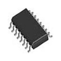
SI3018-F-GSR Silicon Laboratories Inc, SI3018-F-GSR Datasheet - Page 32

SI3018-F-GSR
Manufacturer Part Number
SI3018-F-GSR
Description
Manufacturer
Silicon Laboratories Inc
Datasheet
1.SI3018-F-GSR.pdf
(111 pages)
Specifications of SI3018-F-GSR
Lead Free Status / Rohs Status
Supplier Unconfirmed
- Current page: 32 of 111
- Download datasheet (2Mb)
Si3050 + Si3018/19
The RDT behavior is also based on the RNG1-RNG2
voltage. When the RFWE bit is 0, a positive ring signal
sets the RDT bit for a period of time. When the RFWE
bit is 1, a positive or negative ring signal sets the RDT
bit.
The RDT bit acts like a one shot. When a new ring
signal is detected, the one shot is reset. If no new ring
signals are detected prior to the one shot counter
reaching 0, then the RDT bit clears. The length of this
count is approximately 5 seconds. The RDT bit is reset
to 0 by an off-hook event. If the RDTM bit
(Register 3, bit 7) is set, a hardware interrupt occurs on
the AOUT/INT pin when RDT is triggered. This interrupt
can
(Register 4, bit 7). When the RDI bit (Register 2, bit 2) is
set, an interrupt occurs on both the beginning and end
of the ring pulse as defined by the RTO bits
(Register 23, bits 6:3). Ring validation may be enabled
when using the RDI bit.
The third method to monitor detection uses the DTX
data samples to transmit ring data. If the ISOcap is
active (PDL=0) and the device is not off-hook or in
on-hook line monitor mode, the ring data is presented
on DTX. The waveform on DTX depends on the state of
the RFWE bit.
When RFWE is 0, DTX is –32768 (0x8000) while the
RNG1-RNG2 voltage is between the thresholds. When
a ring is detected, DTX transitions to +32767 when the
ring signal is positive, then goes back to –32768 when
the ring is near 0 and negative. Thus a near square
wave is presented on DTX that swings from –32768 to
+32767 in cadence with the ring signal.
When RFWE is 1, DTX sits at approximately +1228
while the RNG1-RNG2 voltage is between the
thresholds. When the ring becomes positive, DTX
transitions to +32767. When the ring signal goes near 0,
DTX remains near 1228. As the ring becomes negative,
the DTX transitions to –32768. This repeats in cadence
with the ring signal.
To observe the ring signal on DTX, watch the MSB of
the data. The MSB toggles at the same frequency as
the ring signal independent of the ring detector mode.
This method is adequate for determining the ring
frequency.
32
be
cleared
by
writing
to
the
RDTI
Rev. 1.31
bit
5.19. Ring Validation
Ring validation prevents false triggering of a ring
detection by validating the ring parameters. Invalid
signals, such as a line-voltage change when a parallel
handset goes off-hook, pulse dialing, or a high-voltage
line test are ignored. Ring validation can be enabled
during normal operation and in low-power sleep mode
when a valid external PCLK signal is supplied.
The ring validation circuit operates by calculating the
time between alternating crossings of positive and
negative ring thresholds to validate that the ring
frequency is within tolerance. High and low frequency
tolerances are programmable in the RAS[5:0] and
RMX[5:0] fields. The RCC[2:0] bits define how long the
Related parts for SI3018-F-GSR
Image
Part Number
Description
Manufacturer
Datasheet
Request
R
Part Number:
Description:
TSSOP 16/C�/SI3050 GLOBAL VOICE DAA LINE-SIDE - LEAD-FREE
Manufacturer:
Silicon Laboratories Inc
Part Number:
Description:
IC VOICE DAA GCI/PCM/SPI 16TSSOP
Manufacturer:
Silicon Laboratories Inc
Datasheet:

Part Number:
Description:
IC VOICE DAA GCI/PCM/SPI 16SOIC
Manufacturer:
Silicon Laboratories Inc
Datasheet:

Part Number:
Description:
IC VOICE DAA GCI/PCM/SPI 16SOIC
Manufacturer:
Silicon Laboratories Inc
Datasheet:

Part Number:
Description:
Modem Chip Chipset 16-Pin SOIC T/R
Manufacturer:
Silicon Laboratories Inc
Datasheet:
Part Number:
Description:
IC VOICE DAA GCI/PCM/SPI 16SOIC
Manufacturer:
Silicon Laboratories Inc

Part Number:
Description:
IC VOICE DAA GCI/PCM/SPI 16SOIC
Manufacturer:
Silicon Laboratories Inc
Datasheet:

Part Number:
Description:
IC VOICE DAA GCI/PCM/SPI 16SOIC
Manufacturer:
Silicon Laboratories Inc
Datasheet:

Part Number:
Description:
IC VOICE DAA GCI/PCM/SPI 16SOIC
Manufacturer:
Silicon Laboratories Inc
Datasheet:
Part Number:
Description:
IC VOICE DAA GCI/PCM/SPI 16TSSOP
Manufacturer:
Silicon Laboratories Inc
Datasheet:
Part Number:
Description:
IC VOICE DAA GCI/PCM/SPI 16TSSOP
Manufacturer:
Silicon Laboratories Inc
Part Number:
Description:
SMD/C�/SINGLE-ENDED OUTPUT SILICON OSCILLATOR
Manufacturer:
Silicon Laboratories Inc
Part Number:
Description:
Manufacturer:
Silicon Laboratories Inc
Datasheet:
Part Number:
Description:
N/A N/A/SI4010 AES KEYFOB DEMO WITH LCD RX
Manufacturer:
Silicon Laboratories Inc
Datasheet:


