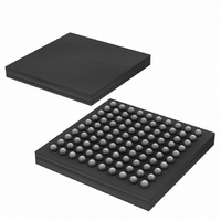
DS3170N+ Maxim Integrated Products, DS3170N+ Datasheet - Page 203

DS3170N+
Manufacturer Part Number
DS3170N+
Description
IC TXRX DS3/E3 100-CSBGA
Manufacturer
Maxim Integrated Products
Datasheet
1.DS3170.pdf
(230 pages)
Specifications of DS3170N+
Function
Single-Chip Transceiver
Interface
DS3, E3
Number Of Circuits
1
Voltage - Supply
3.135 V ~ 3.465 V
Current - Supply
120mA
Operating Temperature
-40°C ~ 85°C
Mounting Type
Surface Mount
Package / Case
100-LBGA
Includes
DS3 Framers, E3 Framers, HDLC Controller, On-Chip BERTs
Lead Free Status / RoHS Status
Lead free / RoHS Compliant
Power (watts)
-
- Current page: 203 of 230
- Download datasheet (3Mb)
13.2 JTAG TAP Controller State Machine Description
This section covers the details on the operation of the Test Access Port (TAP) Controller State Machine. See
Figure 13-2
responds to the logic level at JTMS on the rising edge of JTCLK.
Figure 13-2. JTAG TAP Controller State Machine
Test-Logic-Reset. When JTRST is changed from low to high, the TAP controller starts in the Test-Logic-Reset
state, and the Instruction Register is loaded with the IDCODE instruction. All system logic and I/O pads on the
device operate normally. This state can also be reached from any other state by holding JTMS high and clocking
JTCLK five times.
Run-Test-Idle. Run-Test-Idle is used between scan operations or during specific tests. The Instruction Register
and Test Register remain idle.
Select-DR-Scan. All test registers retain their previous state. With JTMS low, a rising edge of JTCLK moves the
controller into the Capture-DR state and initiates a scan sequence. JTMS high moves the controller to the Select-
IR-Scan state.
for details on each of the states described below. The TAP controller is a finite state machine that
1
0
Test-Logic-Reset
Run-Test/Idle
0
1
1
0
Capture-DR
1
203 of 230
Select
DR-Scan
Shift-DR
Pause-DR
Update-DR
Exit1- DR
Exit2-DR
0
0
1
0
1
1
0
1
0
1
0
DS3170 DS3/E3 Single-Chip Transceiver
1
0
Capture-IR
1
Select
IR-Scan
Shift-IR
Exit1-IR
Pause-IR
Exit2-IR
Update-IR
0
0
1
0
1
1
0
1
0
1
0
Related parts for DS3170N+
Image
Part Number
Description
Manufacturer
Datasheet
Request
R

Part Number:
Description:
IC TXRX DS3/E3 100-CSBGA
Manufacturer:
Maxim Integrated Products
Datasheet:

Part Number:
Description:
Network Controller & Processor ICs DS3-E3 Single-Chip T ransceiver T3-E3 Fra
Manufacturer:
Maxim Integrated Products
Datasheet:

Part Number:
Description:
MAX7528KCWPMaxim Integrated Products [CMOS Dual 8-Bit Buffered Multiplying DACs]
Manufacturer:
Maxim Integrated Products
Datasheet:

Part Number:
Description:
Single +5V, fully integrated, 1.25Gbps laser diode driver.
Manufacturer:
Maxim Integrated Products
Datasheet:

Part Number:
Description:
Single +5V, fully integrated, 155Mbps laser diode driver.
Manufacturer:
Maxim Integrated Products
Datasheet:

Part Number:
Description:
VRD11/VRD10, K8 Rev F 2/3/4-Phase PWM Controllers with Integrated Dual MOSFET Drivers
Manufacturer:
Maxim Integrated Products
Datasheet:

Part Number:
Description:
Highly Integrated Level 2 SMBus Battery Chargers
Manufacturer:
Maxim Integrated Products
Datasheet:

Part Number:
Description:
Current Monitor and Accumulator with Integrated Sense Resistor; ; Temperature Range: -40°C to +85°C
Manufacturer:
Maxim Integrated Products

Part Number:
Description:
TSSOP 14/A°/RS-485 Transceivers with Integrated 100O/120O Termination Resis
Manufacturer:
Maxim Integrated Products

Part Number:
Description:
TSSOP 14/A°/RS-485 Transceivers with Integrated 100O/120O Termination Resis
Manufacturer:
Maxim Integrated Products

Part Number:
Description:
QFN 16/A°/AC-DC and DC-DC Peak-Current-Mode Converters with Integrated Step
Manufacturer:
Maxim Integrated Products

Part Number:
Description:
TDFN/A/65V, 1A, 600KHZ, SYNCHRONOUS STEP-DOWN REGULATOR WITH INTEGRATED SWI
Manufacturer:
Maxim Integrated Products

Part Number:
Description:
Integrated Temperature Controller f
Manufacturer:
Maxim Integrated Products

Part Number:
Description:
SOT23-6/I°/45MHz to 650MHz, Integrated IF VCOs with Differential Output
Manufacturer:
Maxim Integrated Products

Part Number:
Description:
SOT23-6/I°/45MHz to 650MHz, Integrated IF VCOs with Differential Output
Manufacturer:
Maxim Integrated Products


