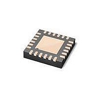
MAX3107ETG+ Maxim Integrated Products, MAX3107ETG+ Datasheet - Page 30

MAX3107ETG+
Manufacturer Part Number
MAX3107ETG+
Description
IC UART SPI/I2C 128 FIFO 24TQFN
Manufacturer
Maxim Integrated Products
Datasheet
1.MAX3107EAG.pdf
(52 pages)
Specifications of MAX3107ETG+
Features
Internal Oscillators
Number Of Channels
4, QUART
Fifo's
128 Byte
Protocol
RS232, RS485
Voltage - Supply
2.35 V ~ 3.6 V
With Auto Flow Control
Yes
With Irda Encoder/decoder
Yes
With False Start Bit Detection
Yes
Mounting Type
Surface Mount
Package / Case
24-TQFN Exposed Pad
Data Rate
24 Mbps
Supply Voltage (max)
3.3 V
Supply Voltage (min)
2.35 V
Supply Current
0.64 mA
Maximum Operating Temperature
+ 85 C
Minimum Operating Temperature
- 40 C
Mounting Style
SMD/SMT
No. Of Channels
1
Uart Features
128-Word Transmit / Receive FIFO, Half-Duplex Echo Suppression, Shutdown And Autosleep Modes
Supply Voltage Range
2.35V To 3.6V
Rohs Compliant
Yes
Lead Free Status / RoHS Status
Lead free / RoHS Compliant
STSIntEn—STS Interrupt Enable Register
STSInt—Status Interrupt Register
SPI/I
and Internal Oscillator
Bits 7 and 4: No Function
Bit 6: SleepIntEn
Set the SleepIntEn bit high to route the SleepInt status bit to the ISR[2]: STSInt. If set low, the STSIntEn masks the ISR[2]
bit from SleepInt.
Bit 5: ClkRdyIntEn
Set the ClkRdyIntEn bit high to route the ClockReady status bit to the ISR[2]: STSInt bit. If set low, the ClkRdyIntEn
masks the ISR[2] bit from the ClockReady status.
Bits 3–0: GPI[3:0]IntEn
The GPI[3:0]IntEn bits that are set high route the associated STSInt[3:0]: GPI[3:0]Int bits to the ISR[2] interrupt. GPI[3:0]
IntEn bits that are set low, mask the ISR[2] interrupt from the associated GPI[3:0]Int bit.
Bits 7 and 4: No Function
Bit 6: SleepInt
The SleepInt bit is set when the MAX3107 enters sleep mode. The SleepInt bit is cleared when the MAX3107 exits sleep
mode. This status bit is cleared when the clock is disabled and cannot be cleared upon reading. The SleepInt bit can
generate an ISR[2]: STSInt interrupt, if enabled through STSIntEn[6].
Bit 5: ClockReady
The ClockReady bit is set high when the clock, the divider, and the PLL have settled, and the MAX3107 is ready for
data communication. The ClockReady bit only works with the internal oscillator or the crystal oscillator. It does not work
with external clocking through XIN.
The ClockReady status bit is cleared when the clock is disabled and is not cleared upon read. This bit can generate
an ISR[2]: STSInt interrupt, if enabled through STSIntEn[5].
Bits 3–0: GPI[3:0]Int
The GPI[3:0]Int interrupts are set high when a change of logic state occurs on the associated GPIO_ input. GPI[3:0]Int
is cleared upon reading. These interrupts can be selectively routed to the ISR[2] interrupt bit through the STSIntEn[3:0].
30
ADDRESS:
MODE:
ADDRESS:
MODE:
RESET
RESET
NAME
NAME
_____________________________________________________________________________________
BIT
BIT
2
C UART with 128-Word FIFOs
—
—
7
0
7
0
0x07
R/W
0x08
R/COR
SleepIntEn
SleepInt
6
0
6
0
ClkRdyIntEn
ClockReady
5
0
5
0
—
—
4
0
4
0
GPI3IntEn
GPI3Int
3
0
3
0
GPI2IntEn
GPI2Int
2
0
2
0
GPI1IntEn
GPI1Int
1
0
1
0
GPI0IntEn
GPI0Int
0
0
0
0


