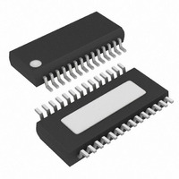
MAX3140EEI+ Maxim Integrated Products, MAX3140EEI+ Datasheet - Page 24

MAX3140EEI+
Manufacturer Part Number
MAX3140EEI+
Description
IC UART W/RS485 28-QSOP
Manufacturer
Maxim Integrated Products
Datasheet
1.MAX3140CEIT.pdf
(36 pages)
Specifications of MAX3140EEI+
Features
Transceiver
Fifo's
8 Byte
Protocol
RS232, RS485
Voltage - Supply
4.75 V ~ 5.25 V
With Irda Encoder/decoder
Yes
With False Start Bit Detection
Yes
With Cmos
Yes
Mounting Type
Surface Mount
Package / Case
28-QSOP
Data Rate
115 Kbps
Supply Voltage (max)
5.25 V
Supply Voltage (min)
4.75 V
Supply Current
0.7 mA
Maximum Operating Temperature
+ 85 C
Minimum Operating Temperature
- 40 C
Mounting Style
SMD/SMT
No. Of Channels
1
Uart Features
Half / Full-Duplex Operation, True Fail-Safe Receiver Output
Supply Voltage Range
4.75V To 5.25V
Rohs Compliant
Yes
Lead Free Status / RoHS Status
Lead free / RoHS Compliant
SPI/MICROWIRE-Compatible UART with Integrated
True Fail-Safe RS-485/RS-422 Transceivers
Example 2: Setting up only the data-available (or data-
being-read) interrupt.
Send the 16-bit word below into DIN of the MAX3140
using the WRITE CONFIGURATION register. This 16-bit
word configures the MAX3140 for 9600bps, 8-bit
words, no parity, and one stop bit with a 1.8432MHz
crystal.
binary 1100010000001010
HEX
The MAX3140 contains a receive FIFO for data received
by the UART to minimize processor overhead. The
receive FIFO is 8 words deep and clears automatically if
it overflows. Shutting down the UART also clears the
receive FIFO. Upon power-up, the receive FIFO is
enabled. To disable the receive FIFO, set the FEN bit
high when writing to the WRITE CONFIGURATION regis-
ter. To check whether the FIFO is enabled or disabled,
read back the FEN bit using the READ CONFIGURA-
TION.
In shutdown, the oscillator turns off to reduce power
consumption (I
shutdown in one of two ways: by a software command
(SHDNi bit = 1) or by a hardware command (SHDN =
logic low). The hardware shutdown immediately termi-
nates any transmission in progress. The software shut-
down, requested by setting SHDNi bit = 1, is entered
upon completing the transmission of the data in both
the transmit-shift register and the transmit-buffer regis-
ter. The SHDNo bit is set when the UART enters shut-
down (either hardware or software). The microcontroller
(µC) can monitor the SHDNo bit to determine when all
data has been transmitted, then shut down RS-485
transceivers at that time.
Shutdown clears the receive FIFO, R, RA/FE, D0r–D7r,
Pr, and Pt registers and sets the T bit high.
Configuration bits (RM, TM, PM, RAM, IR, ST, PE, L, B0-
3, and RTS) can be modified when SHDNo = 1 and
CTS can also be read. Even though RA is reset upon
entering shutdown, it goes high when a transition is
detected on the RX pin. This allows the UART to moni-
tor activity on the receiver when in shutdown.
The command to power up (SHDNi = 0) turns on the
oscillator when CS goes high if SHDN = logic high, with
a start-up time of at least 25ms. This is done by writing
to the WRITE CONFIGURATION register, which clears
all registers but RTS and CTS. Since the crystal oscilla-
tor typically requires at least 25ms to start, the first
received characters can be garbled and a framing
error may occur.
24
______________________________________________________________________________________
C40A
CCSHDN UART
< 1mA). The UART enters
UART Shutdown
Receive FIFO
The RS-485/RS-422 transceiver is equipped with
numerous features allowing it to be configured for any
RS-485/RS-422 application. Figure 10 shows the
MAX3140 functional diagram. Included in the RS-
485/RS-422 transceiver function is full- and half-duplex
selectability, true fail-safe circuitry, programmable
slew-rate limiting, receiver input filtering, and phase
control circuitry.
The MAX3140 operates in either full- or half-duplex
mode. Drive the H/F pin low, leave it unconnected
(internal pull-down), or connect it to GND for full-duplex
operation or drive it high for half-duplex operation. In
half-duplex mode, the receiver inputs are switched to
the driver outputs, connecting outputs Y and Z to inputs
A and B, respectively. In half-duplex mode, the internal
full-duplex receiver input resistors are still connected to
inputs A and B.
The MAX3140 guarantees a logic-high receiver output
when the receiver inputs are shorted or open, or when
they are connected to a terminated transmission line
with all drivers disabled. This is done by setting the
receiver threshold between -50mV and -200mV. If the
differential receiver input voltage (A-B) is greater than
or equal to -50mV, RO is logic high. If A-B is less than
or equal to -200mV, RO is logic low. In the case of a
terminated bus with all transmitters disabled, the
receiver’s differential input voltage is pulled to 0 by the
termination. With the receiver thresholds of the
MAX3140, this results in a logic high with a 50mV mini-
mum noise margin. Unlike previous fail-safe devices,
the -50mV to -200mV threshold complies with the
±200mV EIA/TIA-485 standard.
The MAX3140 has several programmable operating
modes. Transmitter rise and fall times are programma-
ble at 2500ns, 750ns, or 25ns, resulting in maximum
data rates of 115kbps, 500kbps, or 10Mbps, respec-
tively. To select the desired data rate, drive SRL to one
of three possible states by using a three-state driver, by
connecting it to V
nected. For 115kbps operation, set the three-state
device in high-impedance mode or leave SRL uncon-
nected. For 500kbps operation, drive SRL high or con-
nect it to V
connect it to GND. SRL can be changed during opera-
tion without interrupting data communications.
CC
. For 10Mbps operation, drive SRL low or
CC
Programmable Slew-Rate Limiting
RS-485/RS-422 Transceiver
or GND, or by leaving it uncon-
Full Duplex or Half Duplex
True Fail-Safe Circuitry


