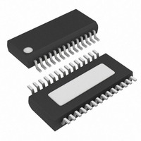
MAX3140EEI+ Maxim Integrated Products, MAX3140EEI+ Datasheet - Page 7

MAX3140EEI+
Manufacturer Part Number
MAX3140EEI+
Description
IC UART W/RS485 28-QSOP
Manufacturer
Maxim Integrated Products
Datasheet
1.MAX3140CEIT.pdf
(36 pages)
Specifications of MAX3140EEI+
Features
Transceiver
Fifo's
8 Byte
Protocol
RS232, RS485
Voltage - Supply
4.75 V ~ 5.25 V
With Irda Encoder/decoder
Yes
With False Start Bit Detection
Yes
With Cmos
Yes
Mounting Type
Surface Mount
Package / Case
28-QSOP
Data Rate
115 Kbps
Supply Voltage (max)
5.25 V
Supply Voltage (min)
4.75 V
Supply Current
0.7 mA
Maximum Operating Temperature
+ 85 C
Minimum Operating Temperature
- 40 C
Mounting Style
SMD/SMT
No. Of Channels
1
Uart Features
Half / Full-Duplex Operation, True Fail-Safe Receiver Output
Supply Voltage Range
4.75V To 5.25V
Rohs Compliant
Yes
Lead Free Status / RoHS Status
Lead free / RoHS Compliant
SWITCHING CHARACTERISTICS—SRL = GND
(V
Note 1: All currents into the device are positive; all currents out of the device are negative. All voltages are referred to device
Note 2: ΔV
Note 3: The SRL pin is internally biased to V
Note 4: Maximum current level applies to peak current just prior to foldback-current limiting; minimum current level applies during
Note 5: The device is put into shutdown by bringing RE high and DE low. If the enable inputs are in this state for less than 50ns, the
SPI/MICROWIRE-Compatible UART with Integrated
Driver Input to Output
Driver Output Skew
|
Driver Rise or Fall Time
Maximum Data Rate
Driver Enable to Output High
Driver Enable to Output Low
Driver Disable Time from Low
Driver Disable Time from High
Receiver Input to Output
|
Receiver Skew
Receiver Enable to Output Low
Receiver Enable to Output High
Receiver Disable Time from Low
Receiver Disable Time from
High
Time to Shutdown
Driver Enable from Shutdown to
Output High
Driver Enable from Shutdown to
Output Low
Receiver Enable from Shutdown
to Output High
Receiver Enable from Shutdown
to Output Low
CC
t
t
DPLH
RPLH
= +5V ±5%, T
- t
- t
ground unless otherwise noted.
current limiting.
device is guaranteed not to enter shutdown. If the enable inputs are in this state for at least 600ns, the device is guaranteed
to have entered shutdown.
PARAMETER
RPHL
DPHL
OD
and ΔV
|
|
Differential
A
_______________________________________________________________________________________
= T
True Fail-Safe RS-485/RS-422 Transceivers
OC
MIN
are the changes in V
to T
MAX
t
t
t
t
, unless otherwise noted. Typical values are at V
DZH(SHDN)
RZH(SHDN)
SYMBOL
DZL(SHDN)
RZL(SHDN)
t
t
DSKEW
DR,
t
t
t
t
t
t
RPLH
SHDN
DPHL
f
t
t
RSKD
t
t
DPLH
t
t
RPHL
t
t
MAX
DZH
DHZ
RZH
RHZ
DZL
DLZ
RZL
RLZ
t
DF
CC
,
OD
/2 by a 100kΩ/100kΩ resistor-divider. It is guaranteed to be V
and V
Figures 3 and 5, R
C
Figures 3 and 5, R
C
Figures 3 and 5, R
C
Figures 4 and 6, C
Figures 4 and 6, C
Figures 4 and 6, C
Figures 4 and 6, C
Figures 7 and 9,
rise and fall time of V
Figures 7 and 9,
rise and fall time of V
Figures 2 and 8, C
Figures 2 and 8, C
Figures 2 and 8, C
Figures 2 and 8, C
(Note 5)
Figures 4 and 6, C
Figures 4 and 6, C
Figures 2 and 8, C
Figures 2 and 8, C
L1
L1
L1
= C
= C
= C
OC
L2
L2
L2
, respectively, when the Dl input changes state.
= 100pF
= 100pF
= 100pF
CONDITIONS
|
|
V
V
DIFF
DIFF
DIFF
L
L
L
L
L
L
L
L
L
L
L
L
ID
ID
= 100pF, S2 closed
= 100pF, S1 closed
= 15pF, S1 closed
= 15pF, S2 closed
= 100pF, S1 closed
= 100pF, S2 closed
= 100pF, S1 closed
= 100pF, S2 closed
= 15pF, S2 closed
= 15pF, S1 closed
= 100pF, S2 closed
= 100pF, S1 closed
ID
ID
|
|
≥ 2.0V,
≥ 2.0V,
= 54Ω,
= 54Ω,
= 54Ω,
≤ 15ns
≤ 15ns
CC
= +5V and T
MIN
10
50
A
= +25°C.)
TYP
-2.5
106
200
CC
34
34
14
20
20
20
20
0
/2 if left unconnected.
MAX
3500
3500
±10
±10
150
150
100
100
150
600
250
250
60
60
25
50
50
50
50
UNITS
Mbps
ns
ns
ns
ns
ns
ns
ns
ns
ns
ns
ns
ns
ns
ns
ns
ns
ns
ns
7


