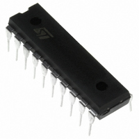
TDA7319 STMicroelectronics, TDA7319 Datasheet - Page 4

TDA7319
Manufacturer Part Number
TDA7319
Description
IC PROCESSOR AUDIO DGTL 20DIP
Manufacturer
STMicroelectronics
Type
Tone and Volume Controlr
Datasheet
1.TDA7319.pdf
(16 pages)
Specifications of TDA7319
Applications
Automotive Audio
Mounting Type
Through Hole
Package / Case
20-DIP (0.300", 7.62mm)
Lead Free Status / RoHS Status
Contains lead / RoHS non-compliant
Other names
497-3970-5
Available stocks
Company
Part Number
Manufacturer
Quantity
Price
Company:
Part Number:
TDA7319
Manufacturer:
BAYLIEAR
Quantity:
12 000
Part Number:
TDA7319
Manufacturer:
ST
Quantity:
20 000
TDA7319
ELECTRICAL CHARACTERISTICS (continued)
Note 1: the device is functionally good at Vs = 5V. A step down, on V
APPLICATION SUGGESTIONS
The first and the last stages are volume control
blocks. The control range is 0 to -47dB (mute)
with a 1dB step.
The very high resolution allows the implementation
of systems free from any noisy acoustical effect.
The TDA7319 audioprocessor provides 3 bands
tones control.
Bass, Middle Stages
The Bass and the middle cells have the same
structure.
The Bass cell has an internal resistor Ri = 44K
typical.
The Middle cell has an internal resistor Ri = 25K
typical.
Several filter types can be implemented, connect-
ing external components to the Bass/Middle IN
and OUT pins.
Figure 1.
4/16
GENERAL
BUS INPUTS
Symbol
S/N
e
V
V
S
E
V
I
NO
d
in
ih
O
C
t
il
C
IN
Output Noise
Total Tracking Error
Signal to Noise Ratio
Channel Separation
Distortion
Input Low Voltage
Input High Voltage
Input Current
Output Voltage SDA
Acknowledge
1
Ri internal
Parameter
R
D95AU313
2
OUT
C
2
All Gains 0dB (B = 20 to 20kHz flat)
A
A
All Gains = 0dB; V
A
V
I
O
V
V
V
in
= 1.6mA
= 0 to -24dB
= -24 to -47dB
= 0; V
= 0.4V
Test Condition
S
in
, to 4V does’t reset the device.
= 1V
The fig.1 refers to basic T Type Bandpass Filter
starting from the filter component values (R1 in-
ternal and R2,C1,C2 external) the centre fre-
quency Fc, the gain Av at max. boost and the fil-
ter Q factor are computed as follows:
Viceversa, once Fc, Av, and Ri internal value are
fixed, the external components values will be:
Treble Stage
The treble stage is a high pass filter whose time
constant is fixed by an internal resistor (25K
typical) and an external capacitor connected be-
tween treble pins and ground
Typical responses are reported in Figg. 10 to 13.
CREF
The suggested 10 F reference capacitor (CREF)
value can be reduced to 4.7 F if the application
requires faster power ON.
rms
O
C1
= 1V
R2
A
rms
2
F
V
C
A
Q
2
V
R2 C2
2
R
1
i
R2 C1
Min.
R2 C1
Ri R2
80
C1 F
-5
Q
3
A
V
Ri, R2,
R2
C
1
1
Typ.
0.01
106
100
C1
R2 C2
0.4
C1 C2
R2 C2
C2
5
0
0
A
Q
C1, C2
V
2
Ri C1
A
Max.
Q
1 Q
0.08
V
0.8
15
1
2
1
5
2
1
C1
Q
2
Unit
dB
dB
dB
dB
%
V
V
V
V
A


