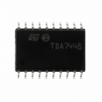
TDA744813TR STMicroelectronics, TDA744813TR Datasheet

TDA744813TR
Specifications of TDA744813TR
Related parts for TDA744813TR
TDA744813TR Summary of contents
Page 1
... IN3 18 IN4 4 IN5 17 IN6 11 GND 20 CREF June 2004 6 CHANNEL VOLUME CONTROLLER Figure 1. Package Table 1. Order Codes TDA744813TR Thanks to the used BIPOLAR/CMOS Technology, Low Distortion, Low Noise and DC stepping are ob- tained. VOLUME 50K VOLUME 50K VOLUME 50K VOLUME 50K VOLUME 50K VOLUME ...
Page 2
TDA7448 Table 2. Absolute Maximum Ratings Symbol V Operating Supply Voltage S T Operating Ambient Temperature amb T Storage Temperature Range stg Figure 3. Pin Connection (Top view) Table 3. Thermal Data Symbol R thermal Resistance junction-pins th j-pin Table ...
Page 3
Table 5. Electrical Characteristcs (refer to the test circuit T = 25°C, V amb Symbol Parameter SUPPLY V Supply Voltage S I Supply Current S SVR Ripple Rejection INPUT STAGE R Input Resistance IN V Clipping Level CL S Input ...
Page 4
TDA7448 Figure 4. Test circuit 0.47 F IN1 0.47 F IN2 0.47 F IN3 0.47 F IN4 0.47 F IN5 0.47 F IN6 APPLICATION SUGGESTIONS The volume control range -79dB, by 1dB step resolution. ...
Page 5
I C BUS INTERFACE Data transmission from microprocessor to the TDA7448 and vice versa takes place through the 2 wires I terface, consisting of the two lines SDA and SCL (pull-up resistors to positive supply voltage must be ...
Page 6
TDA7448 5 SOFTWARE SPECIFICATION Interface Protocol The interface protocol comprises: A start condition (S) A chip address byte, containing the TDA7448 address A subaddress bytes A sequence of data (N byte + acknowledge) A stop condition (P)) CHIP ADDRESS MSB ...
Page 7
In Incremental Bus Mode, the three “not used” functions must be addressed in any case. For example to refresh “ Speaker Attenuation 3 = 0dB and Speaker Attenuation 6 = -40 dB”; the following bytes must be sent: Table 7. ...
Page 8
TDA7448 Figure 11. PIN: CREF Figure 12. PINS 14, 15 OUT1 to OUT6 20 A D02AU1398 Figure 13. PINS 17, 18 100K ...
Page 9
Figure 16. Test and Application Circuit J1 IN1 J3 C1 0.47µF IN1 1 C3 0.47µF 2 IN2 C5 0.47µF IN3 3 C7 0.47µF IN4 4 C9 0.47µF IN5 5 C11 0.47µF IN6 6 C13 10µF 16V GND 7 IC1 TDA7448 ...
Page 10
TDA7448 Figure 17. Component Layout (65 x 72mm) Figure 18. PC Board (Component side) 10/14 ...
Page 11
Figure 19. PC Board (Solder side) TDA7448 11/14 ...
Page 12
TDA7448 Figure 20. SO-20 Mechanical Data & Package Dimensions mm DIM. MIN. TYP. MAX. A 2.35 2.65 A1 0.10 0.30 B 0.33 0.51 C 0.23 0.32 (1) 12.60 13. 7.40 7.60 e 1.27 H 10.0 10.65 h 0.25 ...
Page 13
Table 9. Revision History Date Revision January 2004 June 2004 1 First Issue 3 Modified the style-sheet in compliance with the last revision of the “Corporate Technical Pubblications Design Guide”. Description of Changes TDA7448 13/14 ...
Page 14
... No license is granted by implication or otherwise under any patent or patent rights of STMicroelectronics. Specifications mentioned in this publication are subject to change without notice. This publication supersedes and replaces all information previously supplied. STMicroelectronics products are not authorized for use as critical components in life support devices or systems without express written approval of STMicroelectronics ...


