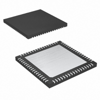
MAX4399CTK+D Maxim Integrated Products, MAX4399CTK+D Datasheet - Page 12

MAX4399CTK+D
Manufacturer Part Number
MAX4399CTK+D
Description
IC SW A/V SCART CON 68-TQFN
Manufacturer
Maxim Integrated Products
Type
Switchr
Datasheet
1.MAX4399CTKTD.pdf
(33 pages)
Specifications of MAX4399CTK+D
Applications
Receivers, Set-Top Boxes, TV
Mounting Type
Surface Mount
Package / Case
68-TQFN Exposed Pad
Lead Free Status / RoHS Status
Lead free / RoHS Compliant
from the Y and C signals to drive the legacy
RF_CVBS_OUT output. The circuit is shown as a sum-
ming point with bias in
and C to get CVBS, and the bias provides the DC levels
for offsetting the chroma signal. Again, loop-through is
not possible with S-VHS because the chroma SCART
pin is used for both input and output.
The MAX4399 supports the CVBS format, with inputs
from the VCR, MPEG decoder, TV, and auxiliary device.
Full loop-through is possible to all devices except the
MPEG decoder because the SCART connector has
separate input and output pins for the CVBS format.
The MAX4399 supports the tri-level slow switching of
IEC 933-1, Amendment 1, which selects the aspect ratio
for the display device. Under I
the MAX4399 sets the slow-switching output levels. Table
1 shows the valid output levels of the slow-switching
signal and the corresponding operating modes of the
display device.
The slow-switching SCART pins are bidirectional. The
MAX4399 can set the slow-switch output drivers to high-
impedance mode to receive signals. When enabled,
INTERRUPT_OUT becomes high impedance if the
voltage level changes on TV_SS, VCR_SS, or AUX_SS.
The VCR or MPEG decoder outputs a fast-switching
signal to the display device. The fast-switching signal
can also be set to a constant high or low through the 2-
wire interface. The pass-through delay from VCR to TV
or MPEG decoder to TV matches that of the RGB sig-
nals facilitating proper OSD insertion.
The DC level at the video outputs is controlled so cou-
pling capacitors are not required, and all of the video
outputs are capable of driving a 150Ω, back-terminated
coax load directly with respect to ground. Since some
televisions and VCRs use the horizontal sync height for
automatic gain control, the MAX4399 accurately repro-
duces the sync height to within ±2%.
The MAX4399 includes an on-chip mixer to produce
CVBS from Y and C. The Y signal input to the mixer has
an external trap filter connection, TRAP, to eliminate the
color subcarrier frequency (4.43MHz), preventing
cross-mixing of the subcarriers in the mixer. TRAP is
internally biased at 0.5V. Connect a series RLC filter to
G_VID, or leave TRAP unconnected if not used.
Audio/Video Switch for Three SCART
Connectors
12
______________________________________________________________________________________
Y/C Mixer and Trap Filter
Figure 2. The MAX4399 sums Y
2
C-compatible control,
Slow Switching
Video Outputs
The audio block has four stereo audio inputs from the TV,
VCR, and AUX SCART connectors, plus the MPEG
decoder. Additionally, the MAX4399 provides a satellite
tone input. Each input has a 100kΩ resistor connected to
an internally generated voltage equal to 0.5 x V_AUD.
There are three main sections—the TV channel, the VCR
channel, and the AUX channel.
Each channel has a stereo output and the TV channel
has an additional phono output and a mono output. The
phono outputs always follow the TV audio input selec-
tion. The mono output, a mix of the TV right and left
channels, drives the channel 3/4 RF modulator. The
three stereo outputs can be configured to normal
mode, swap mode, mono, both channels to right input,
and both channels to left input. The latter two modes
are useful if the left audio channel carries one language
and the right audio channel carries another language.
The phono output is ideal for connection to a hi-fi, and
carries the same signals as the TV output when
switched to normal mode.
The mono mixer, a resistor summer, attenuates the
amplitude of each of the two signals by 6dB. The 3dB
gain block, which follows the mono mixer (Figures 3
and 4), is a compromise between a 0dB gain block and
a 6dB gain block. If the left and right audio channels
were completely uncorrelated, then a 6dB gain block
could be used. If the left and right channels were com-
pletely correlated, then a 0dB block would have to be
used. In reality, most stereo audio channels are partial-
ly correlated and hence a 3dB gain block was used.
Table 1. Slow Switch Modes
SIGNAL VOLTAGE (V)
SLOW-SWITCHING
9.5 to 12.6
4.5 to 7
0 to 2
SCART Audio Switching
Display device uses an internal
source such as a built-in tuner to
provide a video signal
Display device uses a video signal
from the SCART connector and sets
the display to 16:9 aspect ratio
Display device uses a signal from a
SCART connector and sets the
display to 4:3 aspect ratio
MODE
Audio Outputs
Audio Inputs


