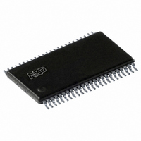
74ALVC16334ADGG;11 NXP Semiconductors, 74ALVC16334ADGG;11 Datasheet - Page 8

74ALVC16334ADGG;11
Manufacturer Part Number
74ALVC16334ADGG;11
Description
IC UNIV BUS DVR 16BIT 48TSSOP
Manufacturer
NXP Semiconductors
Series
74ALVCr
Datasheet
1.74ALVC16334ADGG11.pdf
(12 pages)
Specifications of 74ALVC16334ADGG;11
Logic Type
Universal Bus Driver
Number Of Circuits
16-Bit
Current - Output High, Low
24mA, 24mA
Voltage - Supply
1.2 V ~ 3.6 V
Operating Temperature
-40°C ~ 85°C
Mounting Type
Surface Mount
Package / Case
48-TSSOP
Lead Free Status / RoHS Status
Lead free / RoHS Compliant
Other names
74ALVC16334ADG
74ALVC16334ADG
935267384112
74ALVC16334ADG
935267384112
Philips Semiconductors
AC WAVEFORMS FOR V
V
V
V
V
V
output load.
V
AC WAVEFORMS FOR V
V
V
V
V
V
output load.
V
Waveform 3. Data set-up and hold times for the An input to the
2000 Mar 14
M
X
Y
OL
I
M
X
Y
OL
I
CC
CC
An
INPUT
Waveform 2. Latch enable input (LE) pulse width, the latch
LE
INPUT
NOTE: The shaded areas indicate when the input is permitted to change
= 2.7 V
= V
16-bit registered driver with inverted register enable
(3-State)
= V
= V
= V
= V
Waveform 1. Input (An) to output (Yn) propagation delay
= 1.5 V
= 0.5 V
Yn OUTPUT
GND
GND
and V
and V
V
A
INPUT
GND
V
Y
OUTPUT
V
LE INPUT
= 2.7 V RANGE
< 2.3 V RANGE
CC
V
V
I
n
OH
n
OL
OL
OH
OL
OH
É É É
É É É
É É É
I
I
enable input to output (Yn) propagation delays.
for predictable output performance.
V
GND
+ 0.3 V
+ 0.15 V
V
– 0.3 V
– 0.15 V
V
OH
OH
M
CC
OH
OL
V
= 0.5V
NOTE: V
I
are the typical output voltage drop that occur with the
are the typical output voltage drop that occur with the
NOTE: V
CC
V
M
M
t
at V
V
SU
= 0.5V
M
M
t
PHL
= 0.5 V
CC
V
t
PHL
É É É É É É É
É É É É É É É
É É É É É É É
M
CC
= 2.3 to 2.7 V
th
t
V
W
CC
at V
M
LE input
V
at V
M
CC
V
CC
CC
M
CC
= 2.3 to 2.7 V
= 2.3 to 2.7 V
= 3.0 V TO 3.6 V AND
= 2.3 V TO 2.7 V AND
t
PLH
V
M
t
SU
t
PLH
É É É
É É É
É É É
SH00165
th
SH00132
SH00166
8
Waveform 5. Data set-up and hold times for the An input to the
Waveform 4. The clock (CP) to Yn propagation delays, the
OUTPUT
LOW-to-OFF
OFF-to-LOW
OUTPUT
HIGH-to-OFF
OFF-to-HIGH
Yn OUTPUT
nOE INPUT
Yn OUTPUT
CP INPUT
NOTE: The shaded areas indicate when the input is permitted to change
GND
V
V
CP INPUT
An INPUT
V
GND
NOTE: V
clock pulse width and the maximum clock frequency.
V
OL
OH
CC
I
Waveform 6. 3-State enable and disable times
GND
GND
GND
V
V
V
V
OH
OL
OH
V
for predictable output performance.
OL
M
V
V
V
I
I
I
M
= 0.5V
É É É É
É É É É
É É É É
NOTE: V
= 0.5V
CC
CC
outputs
enabled
V
at V
M
M
at V
t
= 0.5V
PLZ
V
t
V
t
PHZ
PHL
CC
M
M
CC
clock CP input
= 2.3 to 2.7 V
t
W
CC
= 2.3 to 2.7 V
t
su
1/f
at V
V
MAX
É É É É É É É
É É É É É É É
É É É É É É É
M
V
CC
t
X
h
V
Y
= 2.3 to 2.7 V
74ALVC16334A
outputs
disabled
V
M
t
PLH
V
M
Product specification
t
PZL
t
PZH
SH00135
t
su
É É É
É É É
É É É
V
SH00136
M
t
SH00137
V
h
M
outputs
enabled


