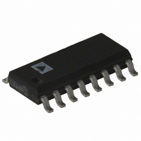
ADE7757ARN Analog Devices Inc, ADE7757ARN Datasheet - Page 12

ADE7757ARN
Manufacturer Part Number
ADE7757ARN
Description
IC ENERGY METERING 16-SOIC
Manufacturer
Analog Devices Inc
Datasheet
1.ADE7757ARNZ.pdf
(16 pages)
Specifications of ADE7757ARN
Rohs Status
RoHS non-compliant
Input Impedance
320 KOhm
Measurement Error
0.1%
Voltage - I/o High
2.4V
Voltage - I/o Low
0.8V
Current - Supply
5mA
Voltage - Supply
4.75 V ~ 5.25 V
Operating Temperature
-40°C ~ 85°C
Mounting Type
Surface Mount
Package / Case
16-SOIC (0.154", 3.90mm Width)
Meter Type
Single Phase
Available stocks
Company
Part Number
Manufacturer
Quantity
Price
Part Number:
ADE7757ARNZ
Manufacturer:
ADI/亚德诺
Quantity:
20 000
Part Number:
ADE7757ARNZRL
Manufacturer:
ADI/亚德诺
Quantity:
20 000
ADE7757
Interfacing the ADE7757 to a Microcontroller for Energy
Measurement
The easiest way to interface the ADE7757 to a microcontroller
is to use the CF high frequency output with the output frequency
scaling set to 2048
and S0 = S1 = 1 (see Table III). With full-scale ac signals on
the analog inputs, the output frequency on CF will be approxi-
mately 2.867 kHz. Figure 14 illustrates one scheme that could
be used to digitize the output frequency and carry out the neces-
sary averaging mentioned in the previous section.
As shown, the frequency output CF is connected to an MCU
counter or port. This will count the number of pulses in a given
integration time, which is determined by an MCU internal timer.
The average power proportional to the average frequency is
given by
The energy consumed during an integration period is given by
For the purpose of calibration, this integration time could be
10 seconds to 20 seconds in order to accumulate enough pulses to
ensure correct averaging of the frequency. In normal opera-
tion, the integration time could be reduced to one or two seconds,
depending, for example, on the required update rate of a dis-
play. With shorter integration times on the MCU, the amount
of energy in each update may still have some small amount of
ripple, even under steady load conditions. However, over a
minute or more the measured energy will have no ripple.
Power Measurement Considerations
Calculating and displaying power information will always have
some associated ripple that will depend on the integration period
used in the MCU to determine average power and also on the
load. For example, at light loads, the output frequency may be
10 Hz. With an integration period of two seconds, only about
20 pulses will be counted. The possibility of missing one pulse
always exists as the ADE7757 output frequency is running
asynchronously to the MCU timer. This would result in a one-
in-twenty or 5% error in the power measurement.
Energy
Figure 14. Interfacing the ADE7757 to an MCU
FREQUENCY
Average Frequency
AVERAGE
ADE7757
Average Power Time
CF
CF
F1, F2. This is done by setting SCF = 0
FREQUENCY
RIPPLE
TIME
Average Power
Counter
Time
COUNTER
TIMER
MCU
Time Counter
Counter
Time
10%
–12–
INTERNAL OSCILLATOR (OSC)
The nominal internal oscillator frequency is 450 kHz when used
with RCLKIN with a nominal value of 6.2 k . The frequency
outputs are directly proportional to the oscillator frequency,
thus RCLKIN must have low tolerance and low temperature
drift to ensure stability and linearity of the chip. The oscillator
frequency is inversely proportional to the RCLKIN as shown in
Figure 15. Although the internal oscillator operates when used
with RCLKIN values between 5.5 k and 20 k , choosing a
value within the range of the nominal value, as shown in Figure 15,
is recommended.
TRANSFER FUNCTION
Frequency Outputs F1 and F2
The ADE7757 calculates the product of two voltage signals (on
Channel V1 and Channel V2) and then low-pass filters this
product to extract real power information. This real power
information is then converted to a frequency. The frequency
information is output on F1 and F2 in the form of active low
pulses. The pulse rate at these outputs is relatively low, e.g.,
0.175 Hz maximum for ac signals with S0 = S1 = 0 (see Table II).
This means that the frequency at these outputs is generated
from real power information accumulated over a relatively long
period of time. The result is an output frequency that is propor-
tional to the average real power. The averaging of the real power
signal is implicit to the digital-to-frequency conversion. The
output frequency or pulse rate is related to the input voltage
signals by the following equation
where
Freq = Output frequency on F1 and F2 (Hz).
V1
V2
V
F
1-4
REF
rms
rms
Figure 15. Effect of RCLKIN on Internal Oscillator
Frequency (OSC)
= Differential rms voltage signal on Channel V1 (V).
= Differential rms voltage signal on Channel V2 (V).
= The reference voltage (2.5 V
= One of four possible frequencies selected by using the
490
480
470
460
450
440
430
420
410
400
logic inputs S0 and S1—see Table I.
5.8
Freq
5.9
6.0
515 84
.
6.1
RESISTANCE – k
6.2
V
1
V
rms
REF
6.3
2
V
2
6.4
8%) (V).
rms
6.5
F
1 4
–
6.6
6.7
REV. A


