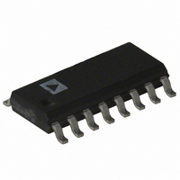
ADE7757ARN Analog Devices Inc, ADE7757ARN Datasheet - Page 9

ADE7757ARN
Manufacturer Part Number
ADE7757ARN
Description
IC ENERGY METERING 16-SOIC
Manufacturer
Analog Devices Inc
Datasheet
1.ADE7757ARNZ.pdf
(16 pages)
Specifications of ADE7757ARN
Rohs Status
RoHS non-compliant
Input Impedance
320 KOhm
Measurement Error
0.1%
Voltage - I/o High
2.4V
Voltage - I/o Low
0.8V
Current - Supply
5mA
Voltage - Supply
4.75 V ~ 5.25 V
Operating Temperature
-40°C ~ 85°C
Mounting Type
Surface Mount
Package / Case
16-SOIC (0.154", 3.90mm Width)
Meter Type
Single Phase
Available stocks
Company
Part Number
Manufacturer
Quantity
Price
Part Number:
ADE7757ARNZ
Manufacturer:
ADI/亚德诺
Quantity:
20 000
Part Number:
ADE7757ARNZRL
Manufacturer:
ADI/亚德诺
Quantity:
20 000
Nonsinusoidal Voltage and Current
The real power calculation method also holds true for
nonsinusoidal current and voltage waveforms. All voltage and
current waveforms in practical applications will have some har-
monic content. Using the Fourier Transform, instantaneous
voltage and current waveforms can be expressed in terms of
their harmonic content.
where:
v(t) is the instantaneous voltage.
V
V
where:
i(t) is the instantaneous current.
I
I
Using Equations 1 and 2, the real power P can be expressed in
terms of its fundamental real power (P
power (P
where
and
As can be seen from Equation 4, a harmonic real power compo-
nent is generated for every harmonic, provided that harmonic is
present in both the voltage and current waveforms. The power
factor calculation has previously been shown to be accurate in
the case of a pure sinusoid. Therefore, the harmonic real power
must also correctly account for power factor since it is made up
of a series of pure sinusoids.
Note that the input bandwidth of the analog inputs is 7 kHz at
the nominal internal oscillator frequency of 450 kHz.
REV. A
0
h
h
h
0
h
is the dc component.
is the rms value of current harmonic h.
is the phase angle of the current harmonic.
is the average value.
is the rms value of voltage harmonic h.
is the phase angle of the voltage harmonic.
v t
i t
P
P
1
1
H
h
H
V
).
h
1
V
I
1
h
0
1
V
0
–
–
I
h
1
1
cos
h
2
I
2
h
cos
h o
1
h o
I
V
h
h
h
P
sin
sin
P
1
h t
h t
P
H
1
) and harmonic real
h
h
(1)
(2)
(3)
(4)
–9–
ANALOG INPUTS
Channel V1 (Current Channel)
The voltage output from the current sensor is connected to the
ADE7757 here. Channel V1 is a fully differential voltage input.
V1P is the positive input with respect to V1N.
The maximum peak differential signal on Channel V1 should be
less than 30 mV (21 mV rms for a pure sinusoidal signal) for
specified operation.
The diagram in Figure 5 illustrates the maximum signal levels
on V1P and V1N. The maximum differential voltage is 30 mV.
The differential voltage signal on the inputs must be referenced
to a common mode, e.g., AGND. The maximum common-
mode signal is 6.25 mV, as shown in Figure 5.
Channel V2 (Voltage Channel)
The output of the line voltage sensor is connected to the
ADE7757 at this analog input. Channel V2 is a fully differen-
tial voltage input with a maximum peak differential signal of
can be connected to the ADE7757 Channel V2.
Channel V2 is usually driven from a common-mode voltage,
i.e., the differential voltage signal on the input is referenced to a
common mode (usually AGND). The analog inputs of the
ADE7757 can be driven with common-mode voltages of up to
25 mV with respect to AGND. However, best results are achieved
using a common mode equal to AGND.
165 mV. Figure 6 illustrates the maximum signal levels that
+165mV
–165mV
+30mV
–30mV
Figure 5. Maximum Signal Levels, Channel V1
Figure 6. Maximum Signal Levels, Channel V2
V
V
CM
CM
V1
V2
DIFFERENTIAL INPUT
DIFFERENTIAL INPUT
165mV MAX PEAK
30mV MAX PEAK
COMMON-MODE
COMMON-MODE
6.25mV MAX
25mV MAX
AGND
AGND
+
–
+
–
+
–
+
–
V1
V
V2
V
CM
CM
V1P
V1N
V2N
ADE7757
V2P


