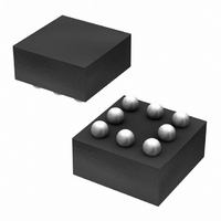
BD6067GU-E2 Rohm Semiconductor, BD6067GU-E2 Datasheet - Page 23

BD6067GU-E2
Manufacturer Part Number
BD6067GU-E2
Description
IC LED DRIVR WHITE BCKLGT 8-VCSP
Manufacturer
Rohm Semiconductor
Type
Backlight, White LEDr
Specifications of BD6067GU-E2
Topology
PWM, Step-Up (Boost)
Number Of Outputs
1
Internal Driver
Yes
Type - Primary
Backlight
Type - Secondary
White LED
Frequency
800kHz ~ 1.2MHz
Voltage - Supply
2.7 V ~ 5.5 V
Voltage - Output
30V
Mounting Type
Surface Mount
Package / Case
8-VCSP
Operating Temperature
-30°C ~ 85°C
Current - Output / Channel
30mA
Internal Switch(s)
Yes
Led Driver Application
Mobile Phones
No. Of Outputs
1
Output Current
30mA
Output Voltage
36V
Input Voltage
2.7V To 5.5V
Operating Temperature Range
-30°C To +85°C
Driver
RoHS Compliant
Lead Free Status / RoHS Status
Lead free / RoHS Compliant
Efficiency
-
Lead Free Status / Rohs Status
Details
Other names
BD6067GU-E2TR
Available stocks
Company
Part Number
Manufacturer
Quantity
Price
Company:
Part Number:
BD6067GU-E2
Manufacturer:
RICOH
Quantity:
3 000
Part Number:
BD6067GU-E2
Manufacturer:
ROHM/罗姆
Quantity:
20 000
© 2011 ROHM Co., Ltd. All rights reserved.
BD6067GU, BD6069GUT, BD6071HFN, BD6072HFN
►BD6069GUT, BD6072HFN
●Setting range of LED current
www.rohm.com
2-2) The brightness adjustment of below is done in adjusting of R2 ON time by R1 and Duty cycle of PWM.
LED current is determined by the voltage of VFB
and the resistor connected to VFB terminal.
I
The current in the standard application is as shown below.
The shaded portion in the figure below is the setting range of LED current to become the standard. Depending on coils and
white LEDs to be used, however, some ICs may not be used at desired currents. Consequently, for the proper setting of LED
current, thoroughly check it for the suitability under use conditions including applicable power supply voltage and
temperature.
LED
The minimum value of the LED current is decided by VFB / R1 at the PWM 0%, the maximum value of the LED current is
decided by VFB / R2 at the PWM 100%.
I
Standard PWM frequency is 100Hz~1kHz. And please don’t use duty less than 5% or more than 95% of current setting for
the brightness adjustment.
LED
is given as shown below.
VIN
I
V
I
is given as shown below.
LED
LED
FB
ILED=VFB / R1 + VFB / R2 × HI Duty
=0.5V, R
=V
=20.8mA
FB
/R
Fig.72 he brightness adjustment example of
VFB terminal by PWM (f
FB
FB
=24Ω
VIN
TEST
EN
GNDA
GND
22µH
VOUT
PWM
1kHz
VFB
SW
PWM
Fig.75 Setting range of LED current
=100Hz~1kHz)
80
70
60
50
40
30
20
10
0
7
47Ω
R2
8
1µF
9 10 11 12 13 14 15 16 17 18
23/29
47Ω
R1
VOUT[V]
VIN
PWM
1µF
Fig.74 Recommended circuit diagram
VIN
EN
TEST
GNDA
25
20
15
10
5
0
0
Fig.73 VFB PWM Control
10 20 30 40 50 60 70 80 90 100
GND
22µH
HI Duty [%]
VOUT
VFB
SW
1µF
2011.01 - Rev.C
Technical Note
RFB
24Ω
ILED


