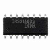
IRS2168DSTRPBF International Rectifier, IRS2168DSTRPBF Datasheet - Page 17

IRS2168DSTRPBF
Manufacturer Part Number
IRS2168DSTRPBF
Description
IC PFC & BALLAST CONTROL 16-SOIC
Manufacturer
International Rectifier
Type
PFC/Ballast Controllerr
Datasheet
1.IRS2168DSTRPBF.pdf
(21 pages)
Specifications of IRS2168DSTRPBF
Frequency
42.5 ~ 46.5 kHz
Current - Supply
10mA
Current - Output
260mA
Voltage - Supply
12.5 V ~ 15.6 V
Operating Temperature
-25°C ~ 125°C
Package / Case
16-SOIC (3.9mm Width)
For Use With
IRPLLNR5 - KIT BALLAST UNIV FLUOR 54W TL5
Lead Free Status / RoHS Status
Lead free / RoHS Compliant
Other names
IRS2168DSTRPBFTR
Available stocks
Company
Part Number
Manufacturer
Quantity
Price
Part Number:
IRS2168DSTRPBF
Manufacturer:
IR
Quantity:
20 000
www.irf.com
When this occurs, V
The IRS2168D enters UVLO mode and both the PFC and
ballast sections are disabled. The start-up supply resistor
to V
should be set such that the ballast turns on at an AC line
input voltage above the level at which the DC bus begins
to drop. The current-sensing resistor at the OC pin sets
the maximum PFC current and therefore sets the
maximum on-time of M
the PFC inductor and programs the minimum low-line
input voltage for the ballast.
resistor to V
pin program the on and off input line voltage thresholds
for the ballast. With these thresholds correctly set, the
ballast will turn off due to the 3.0 V undervoltage
threshold (V
higher voltage (hysterisis) due to the supply resistor to
V
III. Ballast Design Equations
Note: The results from the following design equations can
differ slightly from actual measurements due to IC tol-
erances, component tolerances, and oscillator over- and
under-shoot due to internal comparator response time.
Step 1: Program Run Frequency
The run frequency is programmed with the timing resistor
R
Frequency) to select R
frequency.
Step 2: Program Preheat Frequency
The preheat frequency is programmed with timing
resistors R
connected in parallel for the duration of the preheat time.
Use graph in Fig. 14 (R
R
given as:
CC
FMIN
EQUIV
R
.
140
120
100
80
60
40
20
CC
PH
0
10
at the FMIN pin. Use graph in Fig. 16 (R
, together with the micro-power start-up current,
value for desired preheat frequency. Then R
=
R
R
CC
FMIN
BUSUV-
FMIN
FMIN
and the current-sensing resistor at the OC
Figure 16: f
and R
) on the V
20
−
⋅
CC
R
R
EQUIV
EQUIV
is discharged internally to UVLO.
PFC
PH
FMIN
. This prevents saturation of
FMIN
. The timing resistors are
R
FMIN
BUS
OSC
30
(kW)
vs. Frequency) to select
The micro-power supply
value for desired run
vs R
pin, and on again at a
FMIN
40
[ Ω ]
FMIN
(1)
PH
vs.
50
is
Step 3: Program Preheat Time and Ignition Time
The preheat time is defined by the time it takes for the
external capacitor on pin C
external resistor (R
capacitor C
or
The ignition time is defined by the time it takes for the
external capacitor on pin C
time from V
given as:
Step 4: Program Ignition Ramp Time
The ignition ramp time is defined by the time it takes for
the external capacitor on pin VCO to charge up to 2 V.
The external timing resistor (R
charges capacitor C
therefore given as:
or
Step 5: Program Maximum Ignition Current
The maximum ignition current is programmed with the
external resistor R
(V
of the ballast, which will be reached when the frequency
ramps down towards resonance during ignition and the
lamp does not ignite. The maximum ignition current is
given as:
or
CSTH+
t
C
t
t
C
I
R
). This threshold determines the over-current limit
PH
IGN
RAMP
IGN
VCO
CS
PH
≈
≈
PH
≈
CPHSOI-
≈
≈ 4 .
≈
R
I
. The preheat time is therefore given as:
=
1
R
R
CPH
0
1
t
IGN
t
2 .
CPH
RAMP
R
CS
PH
2 .
R
PH
PH
to V
⋅
⋅
C
t
CS
PH
PH
⋅
CPH
CPHRUN
C
and an internal threshold of 1.2 V
VCO
VCO
) connected to V
. The ignition ramp time is
PH
. The ignition time is therefore
PH
to charge up to V
to charge up the second
PH
IRS2168D(S)PbF
) connected to F
[A] (peak)
[s]
[ Ω ]
[F]
[s]
[F]
[s]
CC
CPHEOP+
(2)
(3)
(4)
(5)
(6)
(7)
(8)
charges
. An
MIN
Page 17


