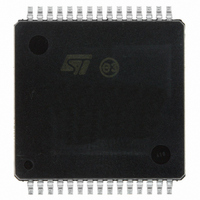
VNH3SP30TR-E STMicroelectronics, VNH3SP30TR-E Datasheet - Page 26

VNH3SP30TR-E
Manufacturer Part Number
VNH3SP30TR-E
Description
IC DRIVER MOTOR H-BRIDGE 30-MPSO
Manufacturer
STMicroelectronics
Type
H-Bridge Motor Driverr
Datasheet
1.VNH3SP30TR-E.pdf
(33 pages)
Specifications of VNH3SP30TR-E
Applications
Automotive
Number Of Outputs
2
Current - Output
30A
Voltage - Supply
5.5 V ~ 36 V
Operating Temperature
-40°C ~ 150°C
Mounting Type
Surface Mount
Package / Case
30-MPSO, MultiPowerSO
Logic Family
VNH3SP30TR-E
Logic Type
H-Bridge Motor Driver
Supply Voltage (max)
40 V
Supply Voltage (min)
- 0.3 V
Maximum Operating Temperature
+ 150 C
Mounting Style
SMD/SMT
Minimum Operating Temperature
- 40 C
Supply Current
15 mA
Operating Current
15mA
Operating Temperature Classification
Automotive
Package Type
MultiPowerSO
Operating Supply Voltage (min)
5.5V
Operating Supply Voltage (max)
36V
Motor Type
Half Bridge
No. Of Outputs
2
Output Current
30A
Supply Voltage Range
5.5V To 36V
Driver Case Style
SOIC
No. Of Pins
30
Operating Temperature Range
-40°C To +150°C
Rohs Compliant
Yes
Lead Free Status / RoHS Status
Lead free / RoHS Compliant
Voltage - Load
-
Lead Free Status / Rohs Status
Lead free / RoHS Compliant
Other names
497-3565-2
VNH3SP30-E
VNH3SP3013TR
VNH3SP30-E
VNH3SP3013TR
Available stocks
Company
Part Number
Manufacturer
Quantity
Price
Company:
Part Number:
VNH3SP30TR-E
Manufacturer:
MEANWELL
Quantity:
4 600
Part Number:
VNH3SP30TR-E
Manufacturer:
ST
Quantity:
20 000
Package and PCB thermal data
4.1.1
4.1.2
4.1.3
4.1.4
b.
26/33
Calculation is valid in any dynamic operating condition. P
Thermal calculation in clockwise and anti-clockwise operation in
steady-state mode
Table 14.
Thermal resistances definition
(values according to the PCB heatsink area)
R
HS
R
R
between High Side and Low Side Chips
R
Chips
Thermal calculation in transient mode
T
T
T
Single pulse thermal impedance definition
(values according to the PCB heatsink area)
Z
Z
Z
between High Side and Low Side Chips
Z
Chips
OFF ON
HS
ON OFF OFF ON
jHSAB
jLSA
jLSB
thHS
thLS
thHSLS
thLSLS
thHS
thLS
thHSLS
thLSLS
B
A
in ON state)
= Z
= Z
= Z
= High Side Chip Thermal Impedance Junction to Ambient
HS
= R
= R
= Z
= Z
= R
= Z
= R
B
thHSLS
thHSLS
thLSA
thHSA
thLSA
thHS
thLSALSB
thHSABLSA
LS
thLSALSB
thHSALSB
ON OFF
Thermal calculation in clockwise and anti-clockwise operation in steady-
state mode
A
= Z
= R
x P
= R
x P
x P
LS
thLSB
dHSAB
thLSB
thHSB
dHSAB
dHSAB
B
= Mutual Thermal Impedance Junction to Ambient between Low Side
= Mutual Thermal Resistance Junction to Ambient between Low Side
= R
= Z
P
x R
P
x R
= Low Side Chip Thermal Impedance Junction to Ambient
dHSA
dHSB
= Low Side Chip Thermal Resistance Junction to Ambient
= High Side Chip Thermal Resistance Junction to Ambient (HS
thHSBLSA
+ Z
thHSABLSB
thHSLS
thHSLS
+ Z
+ Z
thHSLS
x R
x R
thLS
thLSLS
T
jHSAB
thHS
thHS
+ T
+ T
x P
= Mutual Thermal Resistance Junction to Ambient
amb
amb
x (P
= Mutual Thermal Impedance Junction to Ambient
+ P
+ P
x P
d
dLSA
values set by user.
dLSB
dLSA
dLSA
dLSA
+ Z
+ Z
+ P
P
P
P
P
thLSLS
dHSA
dLSB
dHSB
dLSA
thLS
dLSB
(b)
x R
x R
x R
x R
x P
x P
) + T
T
thLSLS
thLS
thHSLS
thHSLS
jLSA
dLSB
dLSB
amb
+ T
+ T
+ T
+ T
+
+
amb
amb
amb
amb
P
x R
P
x R
dHSA
dHSB
thLS
thLSLS
x R
x R
+ T
T
thHSLS
thHSLS
+ T
VNH3SP30-E
amb
jLSB
amb
+ P
+ P
dLSB
dLSA
A
or


