AMIS30623C623BRG ON Semiconductor, AMIS30623C623BRG Datasheet - Page 14
AMIS30623C623BRG
Manufacturer Part Number
AMIS30623C623BRG
Description
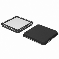
IC MOTOR DRIVER/CTLR 32-QFP
Manufacturer
ON Semiconductor
Datasheet
1.AMIS30623C6239RG.pdf
(61 pages)
Specifications of AMIS30623C623BRG
Applications
Stepper Motor Driver
Number Of Outputs
1
Current - Output
800mA
Voltage - Supply
6.5 V ~ 29 V
Operating Temperature
-40°C ~ 165°C
Mounting Type
Surface Mount
Package / Case
32-VSQFP
Mounting Style
SMD/SMT
Lead Free Status / RoHS Status
Lead free / RoHS Compliant
Voltage - Load
-
Lead Free Status / Rohs Status
Lead free / RoHS Compliant
Available stocks
Company
Part Number
Manufacturer
Quantity
Price
Company:

Part Number:
AMIS30623C623BRG
Manufacturer:
ON Semiconductor
Quantity:
1 850
Company:
Part Number:
AMIS30623C623BRG
Manufacturer:
ON Semiconductor
Quantity:
10 000


•
•
•
block, which provides the required information to the
control logic part. The same applies for detection and
reporting of an electrical problem that could occur on the
coils or the charge pump.
Control Logic (Position Controller and Main Control)
the LIN interface (in a RAM or an OTP memory) and
digitally controls the positioning of the stepper motor in
terms of speed and acceleration, by feeding the right signals
to the motordriver state machine.
commands to properly initiate or stop the stepper motor in
order to reach the set point in a minimum time.
order to manage possible problems and decide on internal
actions and reporting to the LIN interface.
Motion Detection
internally in the running motor. When the motor is blocked,
more detail:
•
•
•
separate chapters.
Battery voltage monitoring is also performed by this
The control logic block stores the information provided by
It will take into account the successive positioning
It also receives feedback from the motordriver part in
Motion detection is based on the back−emf generated
This chapter describes the following functional blocks in
The Motion detection and LIN controller are discussed in
The charge pump to allow driving of the H−bridges’
high side transistors.
Two pre−scale 4−bit DAC’s to set the maximum
magnitude of the current through X and Y.
Two DAC’s to set the correct current ratio through X
and Y.
Position controller
Main control and register, OTP memory + ROM
Motordriver
Hold Current
Zero Speed
Pmin
Ì
Ì
Ì
Ì
Ì
Ì
Ì Ì
Ì Ì
Pstart
Acceleration
range
Figure 7. Positioning and Motion Control
FUNCTIONS DESCRIPTION
http://onsemi.com
14
Vmin
Vmax
Velocity
P=0
e.g. when it hits the end position, the velocity, and as a result
also
AMIS−30623 senses the back−emf, calculates a moving
average and compares the value with two independent
threshold levels. If the back−emf disturbance is bigger than
the set threshold, the running motor is stopped.
LIN Interface
MAC and LLC layers according to the OSI reference model.
It provides and gets information to and from the control logic
block, in order to drive the stepper motor, to configure the
way this motor must be driven, or to get information such as
actual position or diagnosis (temperature, battery voltage,
electrical status...) and pass it to the LIN master node.
Miscellaneous
•
•
•
•
Position Controller
Positioning and Motion Control
illustrated in Figure 7. A motion starts with an acceleration
phase from minimum velocity (Vmin) to maximum velocity
(Vmax) and ends with a symmetrical deceleration. This is
defined by the control logic according to the position
required by the application and the parameters programmed
by the application during the configuration phase. The
current in the coils is also programmable.
The LIN interface implements the physical layer and the
The AMIS−30623 also contains the following:
A positioning command will produce a motion as
An internal oscillator, needed for the LIN protocol
handler as well as the control logic and the PWM
control of the motordriver.
An internal trimmed voltage source for precise
referencing.
A protection block featuring a thermal shutdown and a
power−on−reset circuit.
A 5 V regulator (from the battery supply) to supply the
internal logic circuitry.
the generated back−emf, is disturbed. The
Deceleration
range
Pstop
Ì Ì
Ì Ì
Ì Ì
Ì Ì
Ì Ì
Ì Ì
Ì Ì Ì Ì
Ì Ì Ì Ì
Pmax
Hold Current
Zero Speed
Position
Related parts for AMIS30623C623BRG
Image
Part Number
Description
Manufacturer
Datasheet
Request
R

Part Number:
Description:
ON Semiconductor [VOLTAGE REGULATOR]
Manufacturer:
ON Semiconductor
Datasheet:
Part Number:
Description:
357-036-542-201 CARDEDGE 36POS DL .156 BLK LOPRO
Manufacturer:
ON Semiconductor
Datasheet:
Part Number:
Description:
357-036-542-201 CARDEDGE 36POS DL .156 BLK LOPRO
Manufacturer:
ON Semiconductor
Datasheet:
Part Number:
Description:
357-036-542-201 CARDEDGE 36POS DL .156 BLK LOPRO
Manufacturer:
ON Semiconductor
Datasheet:
Part Number:
Description:
357-036-542-201 CARDEDGE 36POS DL .156 BLK LOPRO
Manufacturer:
ON Semiconductor
Datasheet:
Part Number:
Description:
357-036-542-201 CARDEDGE 36POS DL .156 BLK LOPRO
Manufacturer:
ON Semiconductor
Datasheet:
Part Number:
Description:
357-036-542-201 CARDEDGE 36POS DL .156 BLK LOPRO
Manufacturer:
ON Semiconductor
Datasheet:
Part Number:
Description:
357-036-542-201 CARDEDGE 36POS DL .156 BLK LOPRO
Manufacturer:
ON Semiconductor
Datasheet:
Part Number:
Description:
357-036-542-201 CARDEDGE 36POS DL .156 BLK LOPRO
Manufacturer:
ON Semiconductor
Datasheet:
Part Number:
Description:
357-036-542-201 CARDEDGE 36POS DL .156 BLK LOPRO
Manufacturer:
ON Semiconductor
Datasheet:
Part Number:
Description:
357-036-542-201 CARDEDGE 36POS DL .156 BLK LOPRO
Manufacturer:
ON Semiconductor
Datasheet:
Part Number:
Description:
Manufacturer:
ON Semiconductor
Datasheet:
Part Number:
Description:
Manufacturer:
ON Semiconductor
Datasheet:
Part Number:
Description:
Manufacturer:
ON Semiconductor
Datasheet: