IR5001STRPBF International Rectifier, IR5001STRPBF Datasheet - Page 3
IR5001STRPBF
Manufacturer Part Number
IR5001STRPBF
Description
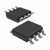
IC CTLR/MOSFET UNIV N-CH 8-SOIC
Manufacturer
International Rectifier
Datasheet
1.IR5001STRPBF.pdf
(12 pages)
Specifications of IR5001STRPBF
Package / Case
8-SOIC (3.9mm Width)
Mounting Type
Surface Mount
Current - Supply
500µA
Voltage - Supply
36 V ~ 75 V
Operating Temperature
0°C ~ 85°C
Applications
-48V Dist Power Systems, AdvancedTCA ® Systems
Number Of Outputs
1
Internal Switch(s)
No
Fet Type
N-Channel
Delay Time - On
27µs
Delay Time - Off
130ns
Operating Temperature (max)
125C
Operating Temperature (min)
-40C
Pin Count
8
Mounting
Surface Mount
Package Type
SOIC N
Screening Level
Automotive
Device Type
O-Ring Controller / MOSFET Driver
Input Delay
27µs
Output Delay
130ns
Driver Case Style
SOIC
No. Of Pins
8
Operating Temperature Range
0°C To +85°C
Rohs Compliant
Yes
Package
8-lead SOIC Narrow
Input Voltage
100V Max Continuous
Vline
36V to 75V 100V Max or 12Vreg
Offset Voltage (v)
-7.9mV min to 0V max
Turn-on Time (ns)
20
Turn-off Time (ns)
130
T Off Gate Drive
3A Peak
Junction Temperature
-40oC to 125oC
Special Ic
FetCheck Available
Lead Free Status / RoHS Status
Lead free / RoHS Compliant
Available stocks
Company
Part Number
Manufacturer
Quantity
Price

Part Number:
IR5001STRPBF
Manufacturer:
IR
Quantity:
20 000


www.irf.com
Note 1: Guaranteed by design but not tested in production.
Note 2: Low Vcc output voltage corresponds to low UVLO voltage
PIN DESCRIPTIONS
Output Section
High Level Output Voltage
Low Level Output Voltage
Turn-On DelayTime
Rise Time
Turn-Off Delay Time
Fall Time
FETch and FETst
FETch Sink Current
FETch Output Delay Time
FETch Threshold
FETst Threshold Voltage
FETst Low Level Output
Voltage
PIN#
1
2
3
4
5
6
7
8
PARAMETERS
PIN SYMBOL
FETch
FETst
Vline
Vout
Vcc
Gnd
INP
INN
IC power supply pin for 36V to 75V input communications systems.
Minimum 25V has to be applied at this pin to bias the IC.
Output pin of the internal shunt regulator, or input pin for biasing the IC via
external resistor. This pin is internally regulated at 12.5V typical. A
minimum 0.1uF capacitor must be connected from this pin to Gnd of IR5001.
FET check input pin. Together with FET status output pin, the FETch pin
can be used to determine the state of the Active ORing circuit and power
system redundancy.
FET status output pin. Together with FETch input pin, the FETst pin can be
used to determine the state of the Active ORing circuit and power system
redundancy.
Positive input of internal comparator. This pin should connect to the source
of N-channel Active ORing MOSFET.
Negative input pin of internal comparator. This pin should connect to the
drain of N-channel Active ORing MOSFET.
Ground pin of the IR5001.
Output pin for the IR5001. This pin is used to directly drive the gate of the
Active Oring N-Channel MOSFET.
Vth(FETch)
Vth(FETst)
FETch_pd
SYMBOL
I(FETch)
Vout LO
Vout HI
td(off)
td(on)
VOL
tr
tf
5k resistor from FETst to 5V logic bias.
V(INP) = Gnd, V(INN) ramping down
Vout switching from LO to HI, Fig.5
Vout switching from HI to LO, Fig.5
from 0 until FETst switches to Low.
IOL=100mA, V(INN)=+0.3V
Isink=1mA, V(INN)=-0.5V
Vline=25V, IOH=50uA,
TEST CONDITION
V(INN)=-0.3V
PIN DESCRIPTION
FETch=5V
Note 1
IR5001S & (PbF)
-525 -300 -200
10.2 11.5 14.1
0.09 0.7
MIN TYP MAX UNITS
-0.5 -1.1
110 130 170
0.9
10
5
0
0.8
1.2
50
27
26
100
0.1
1.8
1.5
45
39
-2
1
mV
ms
mV
uA
us
ns
us
V
V
V
3
Related parts for IR5001STRPBF
Image
Part Number
Description
Manufacturer
Datasheet
Request
R

Part Number:
Description:
IC CTRLR/MOSFET UNIV N-CH 8SOIC
Manufacturer:
International Rectifier
Datasheet:

Part Number:
Description:
SCHOTTKY RECTIFIER
Manufacturer:
International Rectifier Corp.
Datasheet:
Part Number:
Description:
SCHOTTKY RECTIFIER
Manufacturer:
International Rectifier Corp.
Datasheet:
Part Number:
Description:
SCHOTTKY RECTIFIER
Manufacturer:
International Rectifier Corp.
Datasheet:
Part Number:
Description:
SCHOTTKY RECTIFIER
Manufacturer:
International Rectifier Corp.
Datasheet:
Part Number:
Description:
SCHOTTKY RECTIFIER
Manufacturer:
International Rectifier Corp.
Datasheet:
Part Number:
Description:
SCHOTTKY RECTIFIER
Manufacturer:
International Rectifier Corp.
Datasheet:
Part Number:
Description:
SCHOTTKY RECTIFIER
Manufacturer:
International Rectifier Corp.
Datasheet:
Part Number:
Description:
SCHOTTKY RECTIFIER
Manufacturer:
International Rectifier Corp.
Datasheet:
Part Number:
Description:
SCHOTTKY RECTIFIER
Manufacturer:
International Rectifier Corp.
Datasheet:
Part Number:
Description:
SCHOTTKY RECTIFIER
Manufacturer:
International Rectifier Corp.
Datasheet:
Part Number:
Description:
SCHOTTKY RECTIFIER
Manufacturer:
International Rectifier Corp.
Datasheet:
Part Number:
Description:
SCHOTTKY RECTIFIER
Manufacturer:
International Rectifier Corp.
Datasheet:
Part Number:
Description:
SCHOTTKY RECTIFIER
Manufacturer:
International Rectifier Corp.
Datasheet:
Part Number:
Description:
SCHOTTKY RECTIFIER
Manufacturer:
International Rectifier Corp.
Datasheet: