AD636KD Analog Devices Inc, AD636KD Datasheet - Page 11
AD636KD
Manufacturer Part Number
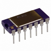
AD636KD
Description
IC TRUE RMS/DC CONV MONO 14-CDIP
Manufacturer
Analog Devices Inc
Datasheet
1.AD636JDZ.pdf
(16 pages)
Specifications of AD636KD
Rohs Status
RoHS non-compliant
Current - Supply
800µA
Voltage - Supply
±2.5 V ~ 16 V
Mounting Type
Through Hole
Package / Case
14-CDIP (0.300", 7.62mm)
Available stocks
Company
Part Number
Manufacturer
Quantity
Price


A COMPLETE AC DIGITAL VOLTMETER
Figure 17 shows a design for a complete low power ac digital
voltmeter circuit based on the AD636. The 10 MΩ input
attenuator allows full-scale ranges of 200 mV, 2 V, 20 V, and
200 V rms. Signals are capacitively coupled to the AD636 buffer
amplifier, which is connected in an ac bootstrapped configuration
to minimize loading. The buffer then drives the 6.7 kΩ input
impedance of the AD636. The COM terminal of the ADC
provides the false ground required by the AD636 for single-
supply operation. An AD589 1.2 V reference diode is used to
provide a stable 100 mV reference for the ADC in the linear
rms mode; in the dB mode, a 1N4148 diode is inserted in series
to provide correction for the temperature coefficient of the dB
scale factor. Calibration of the meter is done by first adjusting
offset trimmer R17 for a proper zero reading, and then
adjusting the R13 for an accurate readout at full scale.
Calibration of the dB range is accomplished by adjusting R9
for the desired 0 dB reference point, and then adjusting R14 for
the desired dB scale factor (a scale of 10 counts per dB is
convenient).
Total power supply current for this circuit is typically 2.8 mA
using a 7106-type ADC.
A LOW POWER, HIGH INPUT, IMPEDANCE dB METER
The portable dB meter circuit combines the functions of the
AD636 rms converter, the AD589 voltage reference, and a
meter offers excellent bandwidth and superior high and low
level accuracy while consuming minimal power from a
standard 9 V transistor radio battery.
In this circuit, the built-in buffer amplifier of the AD636 is
used as a bootstrapped input stage increasing the normal 6.7 kΩ
input Z to an input impedance of approximately 10
Circuit Description
The input voltage, V
with D1 and D2, provide high input voltage protection.
The buffer’s output, Pin 6, is ac-coupled to the rms converter’s
input (Pin 1) by capacitor C2. Resistor R9 is connected between
the buffer’s output, a Class A output stage, and the negative output
swing. Resistor R1 is the amplifier’s bootstrapping resistor.
With this circuit, single-supply operation is made possible by
setting ground at a point between the positive and negative
sides of the battery. This is accomplished by sending 250 μA
from the positive battery terminal through R2, then through the
μA776 low power operational amplifier (see Figure 18). This
IN
, is ac-coupled by C4 while R8, together
10
Ω.
Rev. D | Page 11 of 16
1.2 V AD589 band gap reference, and finally back to the negative
side of the battery via R10. This sets ground at 1.2 V + 3.18 V
(250 μA × 12.7 kΩ) = 4.4 V below the positive battery terminal and
5.0 V (250 μA × 20 kΩ) above the negative battery terminal.
Bypass capacitors, C3 and C5, keep both sides of the battery at a
low ac impedance to ground. The AD589 band gap reference
establishes the 1.2 V regulated reference voltage, which together
with R3 and trimming Potentiometer R4, sets the 0 dB reference
current, I
Performance Data
0 dB Reference Range = 0 dBm (770 mV) to −20 dBm (77 mV) rms
0 dBm = 1 mW in 600 Ω
Input Range (at I
Input Impedance = approximately 10
V
I
Accuracy with 1 kHz sine wave and 9 V dc supply:
Frequency Response ±3 dBm
Input
Calibration
First, calibrate the 0 dB reference level by applying a 1 kHz sine
wave from an audio oscillator at the desired 0 dB amplitude.
This can be anywhere from 0 dBm (770 mV rms − 2.2 V p-p)
to −20 dBm (77 mV rms − 220 mV p-p). Adjust the I
calibration trimmer for a zero indication on the analog meter.
Then, calibrate the meter scale factor or gain. Apply an input
signal −40 dB below the set 0 dB reference and adjust the scale
factor calibration trimmer for a 40 μA reading on the analog meter.
The temperature compensation resistors for this circuit can be
purchased from Micro-Ohm Corporation, 1088 Hamilton Rd.,
Duarte, CA 91010, Part #Type 401F, 2 kΩ ,1% + 3500 ppm/°C.
QUIESCENT
SUPPLY
0 dB to −40 dBm ± 0.1 dBm
0 dBm to −50 dBm ± 0.15 dBm
+10 dBm to −50 dBm ± 0.5 dBm
0 dBm = 5 Hz to 380 kHz
−10 dBm = 5 Hz to 370 kHz
−20 dBm = 5 Hz to 240 kHz
−30 dBm = 5 Hz to 100 kHz
−40 dBm = 5 Hz to 45 kHz
−50 dBm = 5 Hz to 17 kHz
Operating Range = +5 V dc to +20 V dc
REF
= 1. 8 mA typical
.
REF
= 770 mV) = 50 dBm
10
REF
AD636
Related parts for AD636KD
Image
Part Number
Description
Manufacturer
Datasheet
Request
R

Part Number:
Description:
±1.7g Dual-Axis IMEMS Accelerometer Evaluation Board
Manufacturer:
Analog Devices Inc
Datasheet:

Part Number:
Description:
Inertial Sensor Evaluation System
Manufacturer:
Analog Devices Inc
Datasheet:
Part Number:
Description:
Manufacturer:
Analog Devices Inc
Datasheet:
Part Number:
Description:
Manufacturer:
Analog Devices Inc
Datasheet:
Part Number:
Description:
Manufacturer:
Analog Devices Inc
Datasheet:
Part Number:
Description:
Manufacturer:
Analog Devices Inc
Datasheet:
Part Number:
Description:
Manufacturer:
Analog Devices Inc
Datasheet:
Part Number:
Description:
Manufacturer:
Analog Devices Inc
Datasheet:
Part Number:
Description:
Manufacturer:
Analog Devices Inc
Datasheet:
Part Number:
Description:
Manufacturer:
Analog Devices Inc
Datasheet:
Part Number:
Description:
Manufacturer:
Analog Devices Inc
Datasheet:
Part Number:
Description:
Manufacturer:
Analog Devices Inc
Datasheet:
Part Number:
Description:
Manufacturer:
Analog Devices Inc
Datasheet: