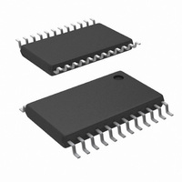
LM81BIMT-3/NOPB National Semiconductor, LM81BIMT-3/NOPB Datasheet - Page 10

LM81BIMT-3/NOPB
Manufacturer Part Number
LM81BIMT-3/NOPB
Description
IC MONITOR SYS HARDWARE 24TSSOP
Manufacturer
National Semiconductor
Datasheet
1.LM81CIMT-3NOPB.pdf
(33 pages)
Specifications of LM81BIMT-3/NOPB
Function
Hardware Monitor
Topology
ADC (Sigma Delta), Comparator, Fan Speed Control, Register Bank
Sensor Type
External & Internal
Sensing Temperature
-40°C ~ 125°C, External Sensor
Output Type
SMBus™
Output Alarm
No
Output Fan
No
Voltage - Supply
2.8 V ~ 3.8 V
Operating Temperature
-40°C ~ 125°C
Mounting Type
Surface Mount
Package / Case
24-TSSOP
Monitored Voltage
2.5 V , 3.3 V , 5 V , 12 V
Manual Reset
Not Resettable
Watchdog
Watchdog
Battery Backup Switching
No
Supply Voltage (max)
3.8 V
Supply Voltage (min)
2.8 V
Supply Current (typ)
400 uA (Typ)
Maximum Operating Temperature
+ 125 C
Minimum Operating Temperature
- 40 C
Power Fail Detection
No
Lead Free Status / RoHS Status
Lead free / RoHS Compliant
Other names
*LM81BIMT-3
*LM81BIMT-3/NOPB
LM81BIMT-3
*LM81BIMT-3/NOPB
LM81BIMT-3
Available stocks
Company
Part Number
Manufacturer
Quantity
Price
Company:
Part Number:
LM81BIMT-3/NOPB
Manufacturer:
CYPRESS
Quantity:
169
Part Number:
LM81BIMT-3/NOPB
Manufacturer:
NS/国半
Quantity:
20 000
www.national.com
Test Circuit
Functional Description
1.0 GENERAL DESCRIPTION
The LM81 provides 6 analog inputs, a temperature sensor, a
Delta-Sigma ADC (Analog-to-Digital Converter), a DAC out-
put, 2 fan speed counters, WATCHDOG registers, and a
variety of inputs and outputs on a single chip. A two wire
Serial Bus interface is included. The LM81 performs power
supply, temperature, fan control and fan monitoring for per-
sonal computers.
The analog inputs are useful for monitoring several power
supplies present in a typical computer. The LM81 includes
internal resistor dividers that scale and/or offset external
Vccp, +2.5V, +3.3V, +5.0V and +12V power supply voltages
to a 3/4 scale nominal ADC output. The LM81 ADC then
continuously converts the scaled inputs to 8-bit digital words.
Measurement of negative voltages (such as -5V and -12V
power supplies) can be accommodated with an external
resistor divider applied to the Vccp2 input. Temperature is
converted to a 9-bit or 12-bit two’s-complement digital word
with a 0.5˚C LSB or 0.0625˚C LSB, respectively.
Fan inputs measure the period of tachometer pulses from
the fans, providing a higher count for lower fan speeds. The
fan inputs are Schmitt-Trigger digital inputs with an accept-
able range of 0V to V
V
represents a stopped or very slow fan. Nominal speeds,
based on a count of 153, are programmable from 1100 to
8800 RPM on FAN1 and FAN2. Schmitt-Trigger input cir-
cuitry is included to accommodate slow rise and fall times. A
0V to 1.25V DAC output voltage range can be used for
control of fan speed.
The LM81 has several internal registers, as shown in Figure
4 , Table 1 and Section 13.0 . These include:
• Configuration Register:
• Interrupt Status Registers:
• Interrupt Mask Registers:
+
/2. Full scale fan counts are 255 (8-bit counter) and this
figuration.
status of each WATCHDOG limit or Interrupt event.
vidual Interrupt sources, as well as separate masking for
each of the two hardware Interrupt outputs.
+
and a transition level of approximately
Provides control and con-
Allows masking of indi-
Two registers to provide
FIGURE 3. Digital Output Load Test Circuitry
10
• CI Clear Register:
• VID/Fan Divisor Register: This register contains the
• Serial Bus Address Register: Contains the Serial Bus
• VID4 Register: Contains the state of the VID4 input.
• Temperature Configuration Register: Selects the in-
• Extended Mode Registers:
• Value RAM:
When the LM81 is started, it cycles through each measure-
ment in sequence, and it continuously loops through the
sequence approximately once every 400 ms. Each mea-
sured value is compared to values stored in WATCHDOG, or
Limit registers. When the measured value violates the pro-
grammed limit the LM81 will set a corresponding Interrupt in
the Interrupt Status Registers. The hardware Interrupt line
INT is fully programmable with separate masking of each
pulse on the chassis intrusion pin (CI).
state of the VID0-VID3 input lines and the divisor bits for
FAN1 and FAN2 inputs.
address. At power on it assumes the default value of
01011XX binary, and can be altered by the state of A0
and A1.
terrupt mode and contains the 0.5˚C LSB of the tempera-
ture reading.
Extended Mode which includes the LSBs of the 12-bit
temperature reading, T_CRIT, and T
(temperature, voltages, fan counts), WATCHDOG limits,
and Company/Stepping IDs are all contained in the Value
RAM. The Value RAM consists of a total of 34 bytes,
addresses 15h - 3Fh, containing:
— byte 1 at address 15h a manufacturers test register
— locations 16h - 18h are unassigned and do not have
— byte 2 at address 19h contains the DAC Data Register
— locations 1Ah - 1Fh are unassigned and do not have
— the next 10 bytes at addresses 20h -29h contain all of
— the next 18 bytes at addresses 2Bh-3Ch are the
— the last 2 bytes at addresses 3Eh and 3Fh contain the
associated registers
associated registers
the results, with address 26h reserved
WATCHDOG limits
Company ID and Stepping ID numbers, respectively
The DAC digital input, monitoring results
Allows transmitting a 20 ms low
Enable and control the
DS100072-6
HYST


