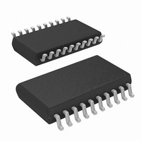
ISL6420IAZ-TK Intersil, ISL6420IAZ-TK Datasheet - Page 12

ISL6420IAZ-TK
Manufacturer Part Number
ISL6420IAZ-TK
Description
IC CTRLR PWM SYNC BUCK 20-QSOP
Manufacturer
Intersil
Datasheet
1.ISL6420IRZ.pdf
(19 pages)
Specifications of ISL6420IAZ-TK
Pwm Type
Voltage Mode
Number Of Outputs
1
Frequency - Max
1.4MHz
Duty Cycle
100%
Voltage - Supply
4.5 V ~ 16 V
Buck
Yes
Boost
No
Flyback
No
Inverting
No
Doubler
No
Divider
No
Cuk
No
Isolated
No
Operating Temperature
-40°C ~ 85°C
Package / Case
20-QSOP
Frequency-max
1.4MHz
Lead Free Status / RoHS Status
Lead free / RoHS Compliant
Available stocks
Company
Part Number
Manufacturer
Quantity
Price
Company:
Part Number:
ISL6420IAZ-TK
Manufacturer:
TI
Quantity:
60
Functional Description
Initialization
The ISL6420 automatically initializes upon receipt of power.
The Power-On Reset (POR) function monitors the internal
bias voltage generated from LDO output (VCC5) and the
ENSS pin. The POR function initiates the soft-start operation
after the VCC5 exceeds the POR threshold. The POR
function inhibits operation with the chip disabled (ENSS
pin <1V).
The device can operate from an input supply voltage of 5.6V
to 16V connected directly to the VIN pin using the internal 5V
linear regulator to bias the chip and supply the gate drivers.
For 5V ±10% applications, connect VIN to VCC5 to bypass
the linear regulator.
Soft-Start/Enable
The ISL6420 soft-start function uses an internal current
source and an external capacitor to reduce stresses and
surge current during startup.
When the output of the internal linear regulator reaches the
POR threshold, the POR function initiates the soft-start
sequence. An internal 10µA current source charges an
external capacitor on the ENSS pin linearly from 0V to 3.3V.
When the ENSS pin voltage reaches 1V typically, the
internal 0.6V reference begins to charge following the dv/dt
of the ENSS voltage. As the soft-start pin charges from 1V to
1.6V, the reference voltage charges from 0V to 0.6V.
Figure 8 shows a typical soft-start sequence.
Overcurrent Protection
The overcurrent function protects the converter from a
shorted output by using the upper MOSFET’s on-resistance,
r
converter’s efficiency and reduces cost by eliminating a
current sensing resistor.
DS(ON)
FIGURE 8. TYPICAL SOFT-START WAVEFORM
to monitor the current. This method enhances the
12
ISL6420
The overcurrent function cycles the soft-start function in a
hiccup mode to provide fault protection. A resistor connected
to the drain of the upper FET and the OCSET pin programs
the overcurrent trip level. The PHASE node voltage will be
compared against the voltage on the OCSET pin, while the
upper FET is on. A current (100µA typically) is pulled from
the OCSET pin to establish the OCSET voltage. If PHASE is
lower than OCSET while the upper FET is on then an over-
current condition is detected for that clock cycle. The upper
gate pulse is immediately terminated, and a counter is incre-
mented. If an overcurrent condition is detected for
8 consecutive clock cycles, and the circuit is not in soft-start,
the ISL6420 enters into the soft-start hiccup mode. During
hiccup, the external capacitor on the ENSS pin is dis-
charged. After the capacitor is discharged, it is released and
a soft-start cycle is initiated. There are three dummy soft-
start delay cycles to allow the MOSFETs to cool down, to
keep the average power dissipation in hiccup mode at an
acceptable level. At the forth soft-start cycle, the output
starts a normal soft-start cycle, and the output tries to ramp.
During soft-start, pulse termination current limiting is
enabled, but the 8-cycle hiccup counter is held in reset until
soft-start is completed. Figure 9 shows the overcurrent hic-
cup mode.
The overcurrent function will trip at a peak inductor current
(I
internal OCSET current source.
The OC trip point varies mainly due to the upper MOSFETs
r
normal operating load range, find the R
the equation above with:
I
DS(ON)
OC
1. The maximum r
2. Determine
OC
VOUT
PHASE
IOUT
temperature.
where ΔI is the output inductor ripple current.
ENSS
) determined from Equation 1, where I
FIGURE 9. TYPICAL OVER-CURRENT HICCUP MODE
=
I
-------------------------------------------------- -
OCSET
variations. To avoid overcurrent tripping in the
R
DS ON
•
I
(
OC
R
OCSET
)
for I
DS(ON)
OC
>
at the highest junction
I
OUT MAX
(
)
+
OCSET
(
ΔI
OCSET
) 2 ⁄
resistor from
,
February 13, 2008
is the
FN9151.5
(EQ. 1)


