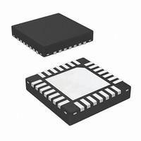
ISL62884CHRTZ Intersil, ISL62884CHRTZ Datasheet - Page 17

ISL62884CHRTZ
Manufacturer Part Number
ISL62884CHRTZ
Description
IC REG PWM SGL PHASE 28WQFN
Manufacturer
Intersil
Datasheet
1.ISL62884CHRTZ.pdf
(30 pages)
Specifications of ISL62884CHRTZ
Applications
Controller, Intel IMVP-6
Voltage - Input
4.5 ~ 25 V
Number Of Outputs
1
Voltage - Output
0.0125 ~ 1.5 V
Operating Temperature
-10°C ~ 100°C
Mounting Type
Surface Mount
Package / Case
28-WQFN
Rohs Compliant
Yes
Lead Free Status / RoHS Status
Lead free / RoHS Compliant
overshoot, forcing the inductor current to freewheel
through the low-side MOSFET body diode. Since the body
diode voltage drop is much higher than MOSFET r
voltage drop, more energy is dissipated on the low-side
MOSFET therefore the output voltage overshoot is lower.
If the overshoot reduction function is enabled, the
ISL62884C monitors the COMP pin voltage to determine
the output voltage overshoot condition. The COMP
voltage will fall and hit the clamp voltage when the
output voltage overshoots. The ISL62884C will turn off
LGATE when COMP is being clamped. The low-side
MOSFET in the power stage will be turned off. When the
output voltage has reached its peak and starts to come
down, the COMP voltage starts to rise and is no longer
clamped. The ISL62884C will resume normal PWM
operation.
While the overshoot reduction function reduces the
output voltage overshoot, energy is dissipated on the
low-side MOSFET, causing additional power loss. The
more frequent the transient event, the more the power
loss dissipated on the low-side MOSFET. The MOSFET
may face severe thermal stress when transient events
occur at a high repetitive rate. User discretion is advised
when this function is enabled.
Key Component Selection
R
The ISL62884C uses a resistor (1% or better tolerance is
recommended) from the RBIAS pin to GND to establish
highly accurate reference current sources inside the IC.
Using R
components to this pin. Do not connect any capacitor to
the RBIAS pin as it will create instability.
Care should be taken in layout that the resistor is placed
very close to the RBIAS pin and that a good quality
signal ground is connected to the opposite side of the
R
Figure 10 shows the inductor DCR current-sensing
network. An inductor current flows through the DCR and
creates a voltage drop. The inductor has a resistors in
R
trace connected to the output-side pad to accurately
sense the inductor current by sensing the DCR voltage
drop. The sensed current information is fed to the NTC
network (consisting of R
C
thermistor, used to temperature-compensate the
inductor DCR change. The inductor current information is
presented to the capacitor C
BIAS
sum
n
BIAS
. R
ntc
connected to the phase-node-side pad and a PCB
resistor.
BIAS
is a negative temperature coefficient (NTC)
= 147kΩ. Do not connect any other
ntcs
17
, R
n
.
ntc
and R
p
) and capacitor
DS(ON)
ISL62884C
Inductor DCR Current-Sensing Network
Equations 6 through 10 describe the frequency-domain
relationship between inductor total current I
voltage V
Transfer function A
inductor DCR value increases as the winding temperature
increases, giving higher reading of the inductor DC
current. The NTC R
temperature decreases. Proper selections of R
R
inductor total DC current over the temperature range of
interest.
There are many sets of parameters that can properly
temperature-compensate the DCR change. Since the
NTC network and the R
divider, V
voltage. It is recommended to have a higher ratio of V
to the inductor DCR voltage, so the droop circuit has
higher signal level to work with.
R
A
ω
V
ω
p
cs
ntcnet
sns
Cn
L
and R
s ( )
=
FIGURE 10. DCR CURRENT-SENSING NETWORK
s ( )
=
DCR
DCR
-------------
=
L
------------------------------------------------------- -
R
----------------------------------------- -
R
=
=
PHASE
L
IO
ntc
---------------------- -
1
ntcnet
ntcnet
cn
Cn
⎛
⎜
⎝
(
----------------------------------------------------
1
R
+
----------------------------------------- -
R
R
+
(s):
is always a fraction of the inductor DCR
ntcnet
ntcs
ntcs
------------ -
ω
parameters ensure that V
------ -
ω
sns
s
s
R
L
×
+
ntcnet
+
+
1
R
R
RSUM
R
R
+
sum
sum
RNTCS
cs
ntc
ntc
RNTC
R
ntc
sum
(s) always has unity gain at DC. The
)
×
+
×
values decreases as its
C
R
sum
R
×
n
p
p
DCR
RP
resistors form a voltage
⎞
⎟
⎠
×
I
o
s ( )
×
Cn
CN
A
+
-
RI
cs
represents the
VCN
s ( )
o
ISUM+
ISUM-
(s) and C
sum
March 16, 2010
, R
(EQ. 10)
FN7591.0
(EQ. 6)
(EQ. 7)
(EQ. 8)
(EQ. 9)
ntcs
cn
n
,


