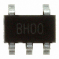
SC4503TSKTRT Semtech, SC4503TSKTRT Datasheet - Page 10

SC4503TSKTRT
Manufacturer Part Number
SC4503TSKTRT
Description
IC SW REG STEP-UP 1.4A TSOT23-5
Manufacturer
Semtech
Type
Step-Up (Boost), Sepicr
Datasheet
1.SC4503TSKTRT.pdf
(22 pages)
Specifications of SC4503TSKTRT
Internal Switch(s)
Yes
Synchronous Rectifier
No
Number Of Outputs
1
Voltage - Output
Adj to 27V
Current - Output
1.4A
Frequency - Switching
1.3MHz
Voltage - Input
2.5 ~ 20 V
Operating Temperature
-40°C ~ 85°C
Mounting Type
Surface Mount
Package / Case
TSOT-23-5, TSOT-5, TSOP-5
Lead Free Status / RoHS Status
Lead free / RoHS Compliant
Power - Output
-
Other names
SC4503TSKTR
Available stocks
Company
Part Number
Manufacturer
Quantity
Price
Company:
Part Number:
SC4503TSKTRT
Manufacturer:
TI
Quantity:
6 000
Part Number:
SC4503TSKTRT
Manufacturer:
SEMTECH/美国升特
Quantity:
20 000
Assuming that the voltage of a nearly discharged Li-ion cell
is 2.6V. Using V
Transient headroom requirement further reduces the maxi-
mum achievable output voltage to below 16V.
Minimum Controllable On-Time
The operating duty cycle of a boost converter decreases as
V
the pulse width in a current-mode switching regulator. This
current ramp is absent unless the switch is turned on. The
intersection of this ramp with the error amplifi er output
determines the switch on-time. The propagation delay
time required to immediately turn off the switch after it is
turned on is the minimum controllable on time. Measured
minimum on time of the SC4503 is load-dependent and
ranges from 180ns to 220ns at room temperature. The
switch in the SC4503 is either not turned on, or, for at least
this minimum. If the regulator requires a switch on-time
less than this controllable minimum, then it will either skip
cycles or start to jitter.
Inductor Selection
The inductor ripple current ΔI
tinuous-conduction mode is
where f is the switching frequency and L is the induc-
tance.
Substituting (3) into (6) and neglecting V
In current-mode control, the slope of the modulating
(sensed switch current) ramp should be steep enough to
2007 Semtech Corp.
POWER MANAGEMENT
Applications Information (Cont.)
IN
∆
approaches V
∆
=
=
=
<
(
−
−
−
−
−
−
D
OUT
=0.5V, V
. Sensed switch current ramp modulates
•
+
)
−
CESAT
−
=0.3V and D=0.86 in (5),
L
of a boost converter in con-
=
CESAT
,
(7)
(5)
(6)
10
lessen jittery tendency but not so steep that large fl ux swing
decreases effi ciency. For continuous-conduction mode
operation, inductor ripple current ΔI
0.6A is a good compromise. Setting ΔI
and f = 1.3MHz in (7),
where L is in μH.
Equation (7) shows that for a given V
when
choose L based on the nominal input voltage.
The saturation current of the inductor should be 20-30%
higher than the peak current limit (1.9 A). Low-cost powder
iron cores are not suitable for high-frequency switching
power supplies due to their high core losses. Inductors
with ferrite cores should be used.
Discontinuous-Conduction Mode
The output-to-input voltage conversion ratio
continuous-conduction mode is limited by the maximum
duty cycle D
Higher voltage conversion ratios can be achieved by oper-
ating the boost converter in full-time discontinuous-con-
duction mode (DCM). Defi ne
output load resistance. The following inequalities must be
satisfi ed for DCM operation:
and,
=
<
<
<
=
∆
=
−
−
−
(
MAX
−
<
:
=
=
+
−
−
+
)
. If V
IN
=
=
=
varies over a wide range, then
R =
V
I
OUT
OUT
L
−
OUT
between 0.35A and
L
= 0.43A, V
, ΔI
as the equivalent
www.semtech.com
SC4503
L
+
is the highest
=
D
= 0.5V
(10)
(8)
(9)
in


