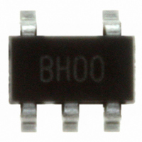
SC4503TSKTRT Semtech, SC4503TSKTRT Datasheet - Page 9

SC4503TSKTRT
Manufacturer Part Number
SC4503TSKTRT
Description
IC SW REG STEP-UP 1.4A TSOT23-5
Manufacturer
Semtech
Type
Step-Up (Boost), Sepicr
Datasheet
1.SC4503TSKTRT.pdf
(22 pages)
Specifications of SC4503TSKTRT
Internal Switch(s)
Yes
Synchronous Rectifier
No
Number Of Outputs
1
Voltage - Output
Adj to 27V
Current - Output
1.4A
Frequency - Switching
1.3MHz
Voltage - Input
2.5 ~ 20 V
Operating Temperature
-40°C ~ 85°C
Mounting Type
Surface Mount
Package / Case
TSOT-23-5, TSOT-5, TSOP-5
Lead Free Status / RoHS Status
Lead free / RoHS Compliant
Power - Output
-
Other names
SC4503TSKTR
Available stocks
Company
Part Number
Manufacturer
Quantity
Price
Company:
Part Number:
SC4503TSKTRT
Manufacturer:
TI
Quantity:
6 000
Part Number:
SC4503TSKTRT
Manufacturer:
SEMTECH/美国升特
Quantity:
20 000
Duty Cycle
The duty cycle D of a boost converter in continuous-conduc-
tion mode (CCM) is:
where V
age drop across the rectifying diode.
Maximum Output Current
In a boost switching regulator the inductor is connected
to the input. The inductor DC current is the input current.
When the power switch is turned on, the inductor current
fl ows into the switch. When the power switch is off, the
inductor current fl ows through the rectifying diode to the
output. The output current is the average diode current.
The diode current waveform is trapezoidal with pulse width
(1 – D)T (see Figure 4). The output current available from
a boost converter therefore depends on the converter oper-
ating duty cycle. The power switch current in the SC4503 is
internally limited to at least 1.4A. This is also the maximum
peak inductor or the peak input current. By estimating the
conduction losses in both the switch and the diode, an
expression of the maximum available output current of a
boost converter can be derived:
2007 Semtech Corp.
POWER MANAGEMENT
Applications Information (Cont.)
Figure 4. Current Waveforms in a Boost Converter
Figure 4. Current Waveforms in a Boost Converter
Figure 4. Current Waveforms in a Boost Converter
Figure 4. Current Waveforms in a Boost Converter
=
CESAT
−
−
=
0
0
0
0
0
0
0
0
Inductor
Inductor
Inductor
Inductor
Current
Current
Current
Current
is the switch saturation voltage and V
ON
ON
ON
ON
+
+
OFF
OFF
OFF
OFF
ON
ON
ON
ON
−
DT
DT
DT
DT
(1-D)T
(1-D)T
(1-D)T
(1-D)T
OFF
OFF
OFF
OFF
−
ON
ON
ON
ON
−
OFF
OFF
OFF
OFF
ON
ON
ON
ON
(
−
Switch Current
Switch Current
Switch Current
Switch Current
ON
ON
ON
ON
Diode Current
Diode Current
Diode Current
Diode Current
)
I
I
I
I
I
I
I
I
IN
IN
IN
IN
OUT
OUT
OUT
OUT
D
is volt-
(3)
(4)
9
where I
It is worth noting that I
ratio
derivation. Equation (4) therefore over-estimates the
maximum output current, however it is a useful fi rst-order
approximation.
Using V
the maximum output current for three V
nations are tabulated (Table 1).
Maximum Duty-Cycle Limitation
The power transistor in the SC4503 is turned off every
switching period for 80ns. This minimum off time limits the
maximum duty cycle of the regulator. A boost converter with
high
cycle. If the required duty cycle is higher than the attain-
able maximum, then the converter will operate in dropout.
(Dropout is a condition in which the regulator cannot attain
its set output voltage below current limit.)
Note: dropout can occur when operating at low input volt-
ages (<3V) and with off times approaching 100ns. Shorten
the PCB trace between the power source and the device
input pin, as line drop may be a signifi cant percentage of
the input voltage. A regulator in dropout may appear as
if it is in current limit. The cycle-by-cycle current limit of
the SC4503 is duty-cycle and input voltage invariant and
should be at least 1.4A. If the converter output is below
its set value and switch current limit is not reached (1.4A),
then the converter is likely in dropout.
Example
when boosting from a single Li-ion cell.
Equation (3) can be re-arranged as:
Table 1. Calculated Maximum Output Currents
Table 1. Calculated Maximum Output Currents
LIM
CESAT
V
V
V
V
:
IN
IN
IN
IN
3.3
3.3
3.3
3.3
3.3
3.3
3.3
3.3
Determine the highest attainable output voltage
is the switch current limit.
5
5
5
5
ratio requires long switch on time and high duty
and that switching losses are neglected in its
(V)
(V)
(V)
(V)
= 0.3V, V
V
V
V
V
OUT
OUT
OUT
OUT
12
12
12
12
12
12
12
12
D
5
5
5
5
= 0.5V and I
(V)
(V)
(V)
(V)
OUTMAX
is directly proportional to the
0.754
0.754
0.754
0.754
0.423
0.423
0.423
0.423
0.615
0.615
0.615
0.615
D
D
D
D
LIM
=1.4A in (3) and (4),
IN
I
I
I
I
and V
www.semtech.com
SC4503
OUT
OUT
OUT
OUT
0.34
0.34
0.34
0.34
0.80
0.80
0.80
0.80
0.53
0.53
0.53
0.53
(A)
(A)
(A)
(A)
OUT
combi-


