ISL8014IRZ Intersil, ISL8014IRZ Datasheet - Page 11

ISL8014IRZ
Manufacturer Part Number
ISL8014IRZ
Description
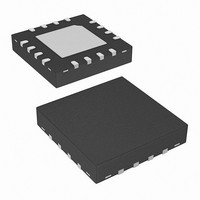
IC REG SYNC BUCK 4A 1MHZ 16-QFN
Manufacturer
Intersil
Type
Step-Down (Buck)r
Datasheet
1.ISL8014IRZ-T.pdf
(16 pages)
Specifications of ISL8014IRZ
Internal Switch(s)
Yes
Synchronous Rectifier
Yes
Number Of Outputs
1
Voltage - Output
0.8 ~ 5.5 V
Current - Output
4A
Frequency - Switching
1MHz
Voltage - Input
2.7 ~ 5.5 V
Operating Temperature
-40°C ~ 85°C
Mounting Type
Surface Mount
Package / Case
16-VQFN Exposed Pad, 16-HVQFN, 16-SQFN, 16-DHVQFN
Lead Free Status / RoHS Status
Lead free / RoHS Compliant
Power - Output
-
Available stocks
Company
Part Number
Manufacturer
Quantity
Price
Company:
Part Number:
ISL8014IRZ
Manufacturer:
Intersil
Quantity:
911
Company:
Part Number:
ISL8014IRZ
Manufacturer:
INTERSIL
Quantity:
700
Part Number:
ISL8014IRZ
Manufacturer:
INTERSIL
Quantity:
20 000
Typical Operating Performance
Theory of Operation
The ISL8014 is a step-down switching regulator
optimized for battery-powered handheld applications.
The regulator operates at 1MHz fixed switching
frequency under heavy load conditions to allow smaller
external inductors and capacitors to be used for minimal
printed-circuit board (PCB) area. At light load, the
regulator reduces the switching frequency, unless forced
to the fixed frequency, to minimize the switching loss and
to maximize the battery life. The quiescent current when
the output is not loaded is typically only 35µA. The
supply current is typically only 0.1µA when the regulator
is shut down.
PWM Control Scheme
Pulling the SYNCH pin HI (>2.5V) forces the converter
into PWM mode, regardless of output current. The
ISL8014 employs the current-mode pulse-width
modulation (PWM) control scheme for fast transient
response and pulse-by-pulse current limiting. Figure 2
shows the block diagram. The current loop consists of the
oscillator, the PWM comparator, current sensing circuit
FIGURE 33. OUTPUT SHORT CIRCUIT
IL 2A/DIV
11
FIGURE 35. OUTPUT CURRENT LIMIT vs TEMPERATURE
5.500
5.375
5.250
5.125
5.000
4.875
4.750
4.625
4.500
-50
V
LX 2V/DIV
OUT
PG 5V/DIV
0.5V/DIV
-25
ISL8014
0
TEMPERATURE (°C)
OCP_3.3V
OCP_5V
(Unless otherwise noted, operating conditions are: T
V
C
VIN
1
and the slope compensation for the current loop stability.
The gain for the current sensing circuit is typically
200mV/A. The control reference for the current loops
comes from the error amplifier's (EAMP) output.
The PWM operation is initialized by the clock from the
oscillator. The P-Channel MOSFET is turned on at the
beginning of a PWM cycle and the current in the
MOSFET starts to ramp up. When the sum of the current
amplifier CSA and the slope compensation (237mV/µs)
reaches the control reference of the current loop, the
PWM comparator COMP sends a signal to the PWM logic
to turn off the P-MOSFET and turn on the N-Channel
MOSFET. The N-MOSFET stays on until the end of the
PWM cycle. Figure 36 shows the typical operating
waveforms during the PWM operation. The dotted lines
illustrate the sum of the slope compensation ramp and
the current-sense amplifier’s CSA output.
The output voltage is regulated by controlling the V
voltage to the current loop. The bandgap circuit outputs
a 0.8V reference voltage to the voltage loop. The
feedback signal comes from the VFB pin. The soft-start
block only affects the operation during the start-up and
25
= 2x22µF, C
IN
= 2.5V to 5.5V, EN = V
IN
FIGURE 34. OUTPUT SHORT CIRCUIT RECOVERY
50
2
= 2x22µF, I
75
100
V
IN
PG 5V/DIV
OUT
OUT
IL 2A/DIV
LX 2V/DIV
, SYNCH = 0V, L = 1.5µH,
1V/DIV
= 0A to 4A)
.
(Continued)
November 23, 2009
A
= +25°C,
FN6576.4
EAMP


