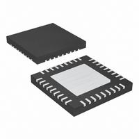
MAX15016AATX+ Maxim Integrated Products, MAX15016AATX+ Datasheet

MAX15016AATX+
Specifications of MAX15016AATX+
Related parts for MAX15016AATX+
MAX15016AATX+ Summary of contents
Page 1
... Space-Saving (6mm x 6mm) Thermally Enhanced 36-Pin TQFN Package PART MAX15014AATX+ -40°C to +125°C 36 TQFN-EP* T3666-3 MAX15014BATX+ MAX15015AATX+ -40°C to +125°C 36 TQFN-EP* T3666-3 MAX15015BATX+ MAX15016AATX+ -40°C to +125°C 36 TQFN-EP* T3666-3 MAX15016BATX+ Applications MAX15017AATX+ -40°C to +125°C 36 TQFN-EP* T3666-3 MAX15017BATX+ + Denotes a lead-free package Exposed pad. ...
Page 2
Input Buck Converters with 50mA Auxiliary LDO Regulators ABSOLUTE MAXIMUM RATINGS IN_SW, IN_LDO, DRAIN, EN_SYS, EN_SW to SGND ..............................................................-0.3V to +45V IN_LDO to IN_SW ..................................................-0.3V to +0. SGND ...........................................-0. PGND ...
Page 3
Input Buck Converters with ELECTRICAL CHARACTERISTICS (continued 14V, V IN_SW IN_LDO DRAIN EN_SYS 1µ 0.1µ 0.1µF, C IN_SW IN_LDO Typical values are +25°C.) ...
Page 4
Input Buck Converters with 50mA Auxiliary LDO Regulators ELECTRICAL CHARACTERISTICS (continued 14V, V IN_SW IN_LDO DRAIN EN_SYS 1µ 0.1µ 0.1µF, C IN_SW IN_LDO Typical values are ...
Page 5
Input Buck Converters with ELECTRICAL CHARACTERISTICS (continued 14V, V IN_SW IN_LDO DRAIN EN_SYS 1µ 0.1µ 0.1µF, C IN_SW IN_LDO Typical values are +25°C.) ...
Page 6
Input Buck Converters with 50mA Auxiliary LDO Regulators ELECTRICAL CHARACTERISTICS (continued 14V, V IN_SW IN_LDO DRAIN EN_SYS 1µ 0.1µ 0.1µF, C IN_SW IN_LDO Typical values are ...
Page 7
Input Buck Converters with ( =14V, V IN_SW IN_LDO DRAIN EN_SYS 1µ 0.1µ 0.1µF, C IN_SW IN_LDO SYSTEM SHUTDOWN CURRENT vs. TEMPERATURE 10 MAX15016 ...
Page 8
Input Buck Converters with 50mA Auxiliary LDO Regulators ( =14V, V IN_SW IN_LDO DRAIN EN_SYS 1µ 0.1µ 0.1µF, C IN_SW IN_LDO TURN-ON/-OFF WAVEFORM INCREASING V IN MAX15014 toc10 ...
Page 9
Input Buck Converters with ( =14V, V IN_SW IN_LDO DRAIN EN_SYS 1µ 0.1µ 0.1µF, C IN_SW IN_LDO LX VOLTAGE AND INDUCTOR CURRENT MAX150_ 2µs/div LX ...
Page 10
Input Buck Converters with 50mA Auxiliary LDO Regulators ( =14V, V IN_SW IN_LDO DRAIN EN_SYS 1µ 0.1µ 0.1µF, C IN_SW IN_LDO DROPOUT VOLTAGE vs. LOAD CURRENT 900 V ...
Page 11
Input Buck Converters with ( =14V, V IN_SW IN_LDO DRAIN EN_SYS 1µ 0.1µ 0.1µF, C IN_SW IN_LDO LDO TURN-ON/-OFF WAVEFORM WITH INCREASING 5mA LOAD 0V ...
Page 12
Input Buck Converters with 50mA Auxiliary LDO Regulators PIN NAME MAX15014/ MAX15015/ MAX15017 MAX15016 12 12, 14, 16, 19, 24, 14, 16, 19, 24, N.C. 26, 27, 30, ...
Page 13
Input Buck Converters with PIN NAME MAX15014/ MAX15015/ MAX15017 MAX15016 — DVREG — SYNC 31 31 COMP REG 36 36 ...
Page 14
Input Buck Converters with 50mA Auxiliary LDO Regulators Detailed Description The MAX15014–MAX15017 combine a voltage-mode buck converter with an internal 0.5Ω power MOSFET switch and a low-quiescent-current LDO regulator. The buck converter of the MAX15015/MAX15016 has ...
Page 15
Input Buck Converters with IN_SW IN_LDO 7.0V OR 4.1V V REFOK V INT V INTOK - 4. REG REG_LDO REFOK V INTOK VINT + V REF VREG_OK UVLO_SW - EN_SW SHDN V V INT ...
Page 16
Input Buck Converters with 50mA Auxiliary LDO Regulators Soft-Start and Reference (SS the 1.235V reference bypass connection for the MAX15014–MAX15017 and also controls the soft-start period. At startup, after input voltage is applied at ...
Page 17
Input Buck Converters with feature a preset output voltage of 5V (MAX1501_A) or 3.3V (MAX1501_B). Alternatively, the output voltage can be adjusted using an external resistive-divider net- work connected between LDO_OUT, SET_LDO, and SGND. See Figure ...
Page 18
Input Buck Converters with 50mA Auxiliary LDO Regulators V ∆ ESR ESR = I + OUT MAX _ I × OUT MAX ∆ × where C is the ...
Page 19
Input Buck Converters with The following equations define the power modulator MOD RAMP × × π × OUT ZESR ...
Page 20
Input Buck Converters with 50mA Auxiliary LDO Regulators f occurs between f and this region, the com pensator gain ( due primarily to C6 and R5. ...
Page 21
... THQ − where V = delay comparator threshold (rising) = CT-TH 1.241V (typ charge current = CT-THQ (typ seconds and Farads Dual Mode is a trademark of Maxim Integrated Products, Inc. ______________________________________________________________________________________ 50mA Auxiliary LDO Regulators and f is approxi therefore × Figure 5. Setting the Output Voltage Using a Resistive Divider 1 − ...
Page 22
Input Buck Converters with 50mA Auxiliary LDO Regulators R6 R3 4.5V TO 40V 40V R4 PGND SGND REG 0.47µF Figure 6. MAX15015/MAX15016 Typical Application Circuit (4.5V ...
Page 23
Input Buck Converters with R6 R3 7.5V TO 40V 7.5V TO 40V R4 PGND SGND REG 0.47µF Figure 7. MAX15014/MAX15017 Typical Application Circuit (7.5V to 40V Input-Voltage Operation) ...
Page 24
Input Buck Converters with 50mA Auxiliary LDO Regulators Pin Configuration TOP VIEW 1 N.C. + N.C. 2 N.C. 3 RESET 4 SGND 5 MAX15014–MAX15017 CT 6 EN_SW 7 EN_SYS 8 EP* N.C. 9 TQFN ( ) ...
Page 25
Input Buck Converters with (The package drawing(s) in this data sheet may not reflect the most current specifications. For the latest package outline information go to www.maxim-ic.com/packages.) ______________________________________________________________________________________ 50mA Auxiliary LDO Regulators Package Information 25 ...
Page 26
... Maxim cannot assume responsibility for use of any circuitry other than circuitry entirely embodied in a Maxim product. No circuit patent licenses are implied. Maxim reserves the right to change the circuitry and specifications without notice at any time. 26 ____________________Maxim Integrated Products, 120 San Gabriel Drive, Sunnyvale, CA 94086 408-737-7600 © 2007 Maxim Integrated Products Package Information (continued registered trademark of Maxim Integrated Products, Inc ...


