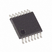
MAX5426AEUD+ Maxim Integrated Products, MAX5426AEUD+ Datasheet - Page 6

MAX5426AEUD+
Manufacturer Part Number
MAX5426AEUD+
Description
IC INSTR AMP PROGR PREC 14-TSSOP
Manufacturer
Maxim Integrated Products
Datasheet
1.MAX5426CEUDT.pdf
(9 pages)
Specifications of MAX5426AEUD+
Applications
*
Mounting Type
Surface Mount
Package / Case
14-TSSOP
Lead Free Status / RoHS Status
Lead free / RoHS Compliant
The MAX5426 is ideal for programmable instrumentation
amplifier applications. The typical application circuit of
Figure 1 uses the MAX5426 in classical instrumentation
amplifier configurations. Two digital inputs set the gain to
1, 2, 4, or 8.
Selection of an op amp for instrumentation amplifier cir-
cuits depends on the accuracy requirements of the
specific application. General guidelines are to choose
an op amp with sufficient open-loop gain, low input-off-
set voltage, and a high common-mode rejection ratio.
High open-loop gain is needed to increase the gain
accuracy, while low input-offset voltage and low input-
offset current help meet gain and offset requirements.
Other parameters such as low input capacitance, low
input bias current, high input common-mode range,
and low noise often need to be considered for a wide
input voltage range stability and AC considerations.
The MAX427 is an excellent choice to use with the
MAX5426.
Precision Resistor Network for
Programmable Instrumentation Amplifiers
Figure 1. Programmable Instrumentation Amplifier Using MAX5426
6
_______________________________________________________________________________________
V
V
CM
D0
D1
Applications Information
IN-
IN+
Op Amp Selection Guidelines
V
V
DD
SS
GND
FB2
FB1
MAX5426
MAX427
MAX427
Figure 2 shows the application of the MAX5426 as a dual
attenuator that can be used in stereo audio systems.
The MAX5426 operates from dual ±5V to ±15V sup-
plies. In many applications the MAX5426 does not
require bypassing. If power-supply noise is excessive,
bypass V
GND.
For best performance, reduce parasitic board capaci-
tance by minimizing the circuit board trace from ampli-
fier outputs to inverting inputs. Also choose op amps
with low input capacitance.
OUT2
OUT1
DD
and V
INDIF-
INDIF+
Stereo Audio-Taper Attenuator
Power Supplies and Bypassing
SS
with 0.1µF ceramic capacitors to
OUT
OFFSET
Layout Concerns
MAX427
V
OUT


